
Perfectly good projects are going off the rails and missing their ship dates, because of worldwide chip shortages, as the world’s FABs focus on pumping out AI chips.
As of mid-2026, 32-bit industrial MCUs and power management ICs are running lead times as long as 52 weeks, driven by AI infrastructure eating into the mature foundry capacity that IoT parts depend on. Automotive-grade MCUs are still sitting at 26 to 40 week lead times through Q2 2026. That’s down from the 52+ week peaks of the prior shortage cycle, but still long enough to force a mid-program part change on most connected products.
That number is the actual argument for a Firmware Abstraction Layer (FAL). Not portability as a design virtue. A parts shortage that arrives mid-program and forces a chip swap on a schedule you don’t control.
When that swap happens, the cost depends entirely on how the firmware was written. If power management calls, event loop timers, and socket buffers are wired straight into the original vendor’s SDK, a driver swap turns into a rewrite. That’s especially true when application code up the stack had no business knowing which chip was underneath it. If none of that is wired in, it’s just a new driver behind an interface that hasn’t changed.
Silicon vendors know this pain point exists, and 2026 has brought real movement. Silicon Labs launched Simplicity SDK for Zephyr at CES 2026, a QA-tested Zephyr distribution built for its wireless chips. The SDK is MCU-agnostic and lets developers mix MCU vendors inside one project, which is a genuine step toward portability rather than a new flavor of lock-in.
Nordic moved in a similar direction with the nRF93M1, announced at MWC 2026, which ships with built-in coexistence control for Wi-Fi and cellular radios sharing one module.
Both of these solve coexistence within a single vendor’s silicon. Coexistence across vendors is a different problem, and it’s still an open problem at the RTOS layer. Zephyr’s Bluetooth stack currently binds to a single controller, so a product can’t natively run Bluetooth radios from two different vendors at once. A proposal to fix that has been open since July 2025, still not shipped.
So vendors are getting better at owning coexistence on their own chips. Managing radios across vendors is still on the OEM to solve, and that’s exactly what a FAL is for.
List every radio in the product, whether that’s BLE, Wi-Fi, cellular, or UWB. For each one, write down the vendor, the SDK version, and the frequency band it operates in.
Then map where they can interfere with each other. A Wi-Fi transmission can wipe out an incoming BLE advertising packet on the same band. A cellular modem waking up for a paging window can starve a UWB ranging session of power budget. These collisions come from physics, not software architecture, and a single vendor’s SDK has no idea another radio even exists on the board.
This inventory is the spec for everything that follows. Skip it and you’ll end up designing an abstraction layer for radios that don’t actually fight each other, while missing the pair that does.
Vendor SDKs manage power per radio. BLE connection intervals, cellular eDRX timers, and Wi-Fi power-save modes each get handled separately, by their own SDK, with no visibility into what the other radios are doing at the same moment.
Replace that with one system-level state machine that every radio driver reports into. Two states cover most products, System_Sleep() and System_Active(). Before switching states, the FAL checks every active radio and picks the lowest power level that all of them can safely handle.
Work out the timing rules on paper first. Decide which radio’s constraints are allowed to hold up a sleep transition and which aren’t. If you get this wrong, you’ll spend the second half of the project chasing power bugs that only show up once two radios are active together.
A cellular modem times out silently over several seconds. A BLE driver drops the connection instantly with a stack-specific status code that means nothing outside that SDK. If you leave this alone, the application layer will fill up with chip-specific if/else branches for every vendor you’ve ever integrated.
Translate every vendor error into a small set of system-level states instead, things like LINK_TEMPORARY_LOSS or HARDWARE_UNRESPONSIVE. The application layer reacts to these states and never has to know what a specific vendor’s error code means.
This step tends to have the biggest payoff for the smallest amount of code, which is also why teams skip it first under deadline pressure. It doesn’t block a demo. It blocks the fifth product revision, when nobody on the team remembers which vendor’s error code meant what.
Antenna sharing, board-level power rails, shared bus access. When two radios need the same physical resource at the same moment, something has to decide who goes first, and that decision can’t be left to whichever driver happened to initialize last.
Build a single arbitration component that owns every shared resource on the board, and routes every radio driver’s requests through it. Don’t let a driver talk to a shared antenna switch or a shared power rail directly, even when the vendor SDK makes that shortcut tempting.
Most of your real RF debugging time during bring-up ends up here anyway. A clean arbitration boundary keeps those bugs in one file instead of scattered across three different vendor codebases.
Radio firmware updates need their own execution pipe, separate from application code. A failed radio firmware update shouldn’t be able to take down the rest of the product. And when only a wireless component changes, keeping the update isolated means regulatory recertification stays scoped to the radio abstraction module instead of pulling your whole application layer back into scope.
The cost difference here is real. A pre-certified wireless module cuts FCC certification cost by 60 to 80 percent and roughly halves the timeline compared with a custom RF design. Keep the split clean and a wireless-only change stays a wireless-only filing. Mix it with application code, and the whole product can get pulled back into certification scope.
If your OTA pipeline currently pushes application code and radio firmware through the same mechanism, split them now, while it’s a small job, rather than during a hardware revision, when it isn’t a small job anymore.
There’s a live example of this on the Zephyr project. A team building on an NXP 88W8987 Wi-Fi combo module wants to add Bluetooth, and the open issue confirms there’s no upstream Bluetooth HCI driver for that chip, even though the Wi-Fi side already works.
The thread lays out three options. Add a second Bluetooth chip from a different vendor. Work from an unofficial vendor driver outside the mainline Zephyr tree. Or redesign the hardware around a different combo chip entirely, which the thread notes isn’t always possible once BOM, supply chain, and certification decisions are already locked in.
Every one of those options costs something, and the reason the team is stuck choosing between them is that nobody drew the FAL boundary early enough. A team that already has a power state machine, an error taxonomy, and an arbitration layer in place can absorb a second radio vendor as a driver-level change. A team without one ends up making this decision in a GitHub comment thread, mid-project, instead of in a design review months earlier. Our previous post goes more into this – Architecting Multi-Radio Embedded Devices with BLE, Wi-Fi, LTE, and UWB.
You don’t need to own every layer for every product. What matters is deciding, for each of the four systems above, whether you build it yourself or lean on the vendor SDK.
If you’re shipping on a single vendor’s chip for a short product life, with no planned cost-down or radio swap, take the vendor’s SDK as it comes, coexistence tools included. The speed advantage is real, and there’s no multi-vendor problem to solve.
If you’re running radios from more than one silicon supplier, this applies to you. It also applies if you’re building a product line meant to last three to seven years through component shortages and cost-downs. Build the power state machine, error taxonomy, arbitration layer, and OTA isolation yourself. Leave everything else on the vendor SDK.
Most teams don’t need to build a FAL from scratch. They need these boundaries drawn correctly before the second radio vendor shows up as a surprise instead of a plan.
Multi-radio products get harder to maintain when the boundaries between vendor firmware and system firmware are unclear. Defining those boundaries early gives your team more options when hardware, suppliers, or product requirements change.
embedUR brings 20 years of experience building wireless stacks, controller firmware, and cross-vendor abstractions for connected products. If you’re planning a multi-radio product or preparing for a hardware refresh, our engineering team can help you define the right firmware boundaries.
Schedule a Firmware Architecture Review with our experts and protect your product roadmap against silicon delays, unexpected chip swaps, and costly recertification cycles.
Perfectly good projects are going off the rails and missing their ship dates, because of worldwide chip shortages, as the world’s FABs focus on pumping out AI chips.
As of mid-2026, 32-bit industrial MCUs and power management ICs are running lead times as long as 52 weeks, driven by AI infrastructure eating into the mature foundry capacity that IoT parts depend on. Automotive-grade MCUs are still sitting at 26 to 40 week lead times through Q2 2026. That’s down from the 52+ week peaks of the prior shortage cycle, but still long enough to force a mid-program part change on most connected products.
That number is the actual argument for a Firmware Abstraction Layer (FAL). Not portability as a design virtue. A parts shortage that arrives mid-program and forces a chip swap on a schedule you don’t control.
When that swap happens, the cost depends entirely on how the firmware was written. If power management calls, event loop timers, and socket buffers are wired straight into the original vendor’s SDK, a driver swap turns into a rewrite. That’s especially true when application code up the stack had no business knowing which chip was underneath it. If none of that is wired in, it’s just a new driver behind an interface that hasn’t changed.
Silicon vendors know this pain point exists, and 2026 has brought real movement. Silicon Labs launched Simplicity SDK for Zephyr at CES 2026, a QA-tested Zephyr distribution built for its wireless chips. The SDK is MCU-agnostic and lets developers mix MCU vendors inside one project, which is a genuine step toward portability rather than a new flavor of lock-in.
Nordic moved in a similar direction with the nRF93M1, announced at MWC 2026, which ships with built-in coexistence control for Wi-Fi and cellular radios sharing one module.
Both of these solve coexistence within a single vendor’s silicon. Coexistence across vendors is a different problem, and it’s still an open problem at the RTOS layer. Zephyr’s Bluetooth stack currently binds to a single controller, so a product can’t natively run Bluetooth radios from two different vendors at once. A proposal to fix that has been open since July 2025, still not shipped.
So vendors are getting better at owning coexistence on their own chips. Managing radios across vendors is still on the OEM to solve, and that’s exactly what a FAL is for.
List every radio in the product, whether that’s BLE, Wi-Fi, cellular, or UWB. For each one, write down the vendor, the SDK version, and the frequency band it operates in.
Then map where they can interfere with each other. A Wi-Fi transmission can wipe out an incoming BLE advertising packet on the same band. A cellular modem waking up for a paging window can starve a UWB ranging session of power budget. These collisions come from physics, not software architecture, and a single vendor’s SDK has no idea another radio even exists on the board.
This inventory is the spec for everything that follows. Skip it and you’ll end up designing an abstraction layer for radios that don’t actually fight each other, while missing the pair that does.
Vendor SDKs manage power per radio. BLE connection intervals, cellular eDRX timers, and Wi-Fi power-save modes each get handled separately, by their own SDK, with no visibility into what the other radios are doing at the same moment.
Replace that with one system-level state machine that every radio driver reports into. Two states cover most products, System_Sleep() and System_Active(). Before switching states, the FAL checks every active radio and picks the lowest power level that all of them can safely handle.
Work out the timing rules on paper first. Decide which radio’s constraints are allowed to hold up a sleep transition and which aren’t. If you get this wrong, you’ll spend the second half of the project chasing power bugs that only show up once two radios are active together.
A cellular modem times out silently over several seconds. A BLE driver drops the connection instantly with a stack-specific status code that means nothing outside that SDK. If you leave this alone, the application layer will fill up with chip-specific if/else branches for every vendor you’ve ever integrated.
Translate every vendor error into a small set of system-level states instead, things like LINK_TEMPORARY_LOSS or HARDWARE_UNRESPONSIVE. The application layer reacts to these states and never has to know what a specific vendor’s error code means.
This step tends to have the biggest payoff for the smallest amount of code, which is also why teams skip it first under deadline pressure. It doesn’t block a demo. It blocks the fifth product revision, when nobody on the team remembers which vendor’s error code meant what.
Antenna sharing, board-level power rails, shared bus access. When two radios need the same physical resource at the same moment, something has to decide who goes first, and that decision can’t be left to whichever driver happened to initialize last.
Build a single arbitration component that owns every shared resource on the board, and routes every radio driver’s requests through it. Don’t let a driver talk to a shared antenna switch or a shared power rail directly, even when the vendor SDK makes that shortcut tempting.
Most of your real RF debugging time during bring-up ends up here anyway. A clean arbitration boundary keeps those bugs in one file instead of scattered across three different vendor codebases.
Radio firmware updates need their own execution pipe, separate from application code. A failed radio firmware update shouldn’t be able to take down the rest of the product. And when only a wireless component changes, keeping the update isolated means regulatory recertification stays scoped to the radio abstraction module instead of pulling your whole application layer back into scope.
The cost difference here is real. A pre-certified wireless module cuts FCC certification cost by 60 to 80 percent and roughly halves the timeline compared with a custom RF design. Keep the split clean and a wireless-only change stays a wireless-only filing. Mix it with application code, and the whole product can get pulled back into certification scope.
If your OTA pipeline currently pushes application code and radio firmware through the same mechanism, split them now, while it’s a small job, rather than during a hardware revision, when it isn’t a small job anymore.
There’s a live example of this on the Zephyr project. A team building on an NXP 88W8987 Wi-Fi combo module wants to add Bluetooth, and the open issue confirms there’s no upstream Bluetooth HCI driver for that chip, even though the Wi-Fi side already works.
The thread lays out three options. Add a second Bluetooth chip from a different vendor. Work from an unofficial vendor driver outside the mainline Zephyr tree. Or redesign the hardware around a different combo chip entirely, which the thread notes isn’t always possible once BOM, supply chain, and certification decisions are already locked in.
Every one of those options costs something, and the reason the team is stuck choosing between them is that nobody drew the FAL boundary early enough. A team that already has a power state machine, an error taxonomy, and an arbitration layer in place can absorb a second radio vendor as a driver-level change. A team without one ends up making this decision in a GitHub comment thread, mid-project, instead of in a design review months earlier. Our previous post goes more into this – Architecting Multi-Radio Embedded Devices with BLE, Wi-Fi, LTE, and UWB.
You don’t need to own every layer for every product. What matters is deciding, for each of the four systems above, whether you build it yourself or lean on the vendor SDK.
If you’re shipping on a single vendor’s chip for a short product life, with no planned cost-down or radio swap, take the vendor’s SDK as it comes, coexistence tools included. The speed advantage is real, and there’s no multi-vendor problem to solve.
If you’re running radios from more than one silicon supplier, this applies to you. It also applies if you’re building a product line meant to last three to seven years through component shortages and cost-downs. Build the power state machine, error taxonomy, arbitration layer, and OTA isolation yourself. Leave everything else on the vendor SDK.
Most teams don’t need to build a FAL from scratch. They need these boundaries drawn correctly before the second radio vendor shows up as a surprise instead of a plan.
Multi-radio products get harder to maintain when the boundaries between vendor firmware and system firmware are unclear. Defining those boundaries early gives your team more options when hardware, suppliers, or product requirements change.
embedUR brings 20 years of experience building wireless stacks, controller firmware, and cross-vendor abstractions for connected products. If you’re planning a multi-radio product or preparing for a hardware refresh, our engineering team can help you define the right firmware boundaries.
Schedule a Firmware Architecture Review with our experts and protect your product roadmap against silicon delays, unexpected chip swaps, and costly recertification cycles.
A product can pass every test in the lab and still fail in a customer’s hands, for a reason that has nothing to do with bad code, bad luck, or a faulty chip. It happens more often than most engineering teams realize, and almost every time, the real cause turns out to be the same thing.
Picture a device that runs Bluetooth, Wi-Fi, and an AI model, all built into one chip. In the lab, each of these was tested on its own, and each one performed exactly as the datasheet promised. The product shipped. Then customers started reporting dropped connections, batteries draining faster than expected, and the occasional unexplained reset.
Nobody could reproduce it reliably. The hardware checked out fine every time it was inspected. The firmware passed every review. And yet, in the field, the product simply did not behave the way it had in the lab.
Here is what was actually happening. Bluetooth, Wi-Fi, and the AI model were each managing their own power independently, the way radios have always done. Each one woke up, did its job, and went back to sleep, entirely on its own schedule, with no idea what the other two were doing at the same moment.
Most of the time, that was fine. But often, all three would wake up within the same few milliseconds, drawing power from the same shared battery supply at the same instant. When that happened, the battery couldn’t quite keep up, and the voltage dipped just enough to cause a dropped packet, a missed connection, or a reset that looked, from the outside, like it came from nowhere.
That is the entire problem, in one sentence: nobody had told the three of them to take turns.
A few years ago, this simply wasn’t an issue, because it wasn’t physically possible for it to be one. Wireless radios and AI processing usually lived on separate chips, each with its own power supply, completely unaware of the other’s existence. If one drew a spike of current, it had no effect on the other, because they weren’t sharing anything.
That has changed. Modern chips now combine Wi-Fi, Bluetooth, sometimes Thread or Zigbee as well, and a dedicated AI processor, typically an NPU, or Neural Processing Unit, built specifically to run AI models efficiently, all on a single piece of silicon.
Each part of that chip still has its own settings for when to sleep and when to wake, but all of them draw from the same underlying power supply. What looks, on a spec sheet, like several independent components is, in practice, one shared electrical system with several tenants who don’t talk to each other.
That is the shift that created this problem, and it has happened recently across almost every category of connected product.
Most people think the AI Model is the power hog. It may be the memory hog, but it is not the power hog people think. Here is something worth knowing before going further, because it changes where the real risk actually sits.
Engineering teams may assume the AI model is the power-hungry part of the system, since it is the newest and most computationally demanding piece. It usually is not. An analysis compared how much power each part of a typical device draws:
a) Running the AI model, on average: 10 to 100 microwatts
b) Sending a single Bluetooth transmission: 10 to 50 milliwatts, up to 5000 times more than the AI model
c) Sending a single Wi-Fi transmission: 200 to 1000 milliwatts or more, up to a million times more than the AI model
The radios, not the AI, are where almost all of the power goes. Which means a team that spends weeks trimming the AI model to save power is optimising the smallest number on the board, while the two components that actually drive battery life keep operating with no coordination between them at all.
If this were a rare edge case, it might not be worth an article. It isn’t rare, and it’s becoming common every year.
Chip makers are racing to put more of these components on a single die, because customers want smaller, cheaper, more capable products. One of our semiconductor partners, Synaptics, recently launched a chip that combines Wi-Fi, Bluetooth, and a dedicated AI processor on a single piece of silicon.
Another partner, NXP, has done something similar, pairing its processors with dedicated AI accelerators on the same chip. Every one of these announcements makes the underlying problem more common, because every one of them puts more shared tenants on the same electrical supply.
The chip makers can build better individual components. They cannot decide, from inside the silicon, whether a Wi-Fi transmission should wait two milliseconds for a Bluetooth connection to finish first. That decision has to be made by whoever builds the product, in software, because no chip on the market makes that call on its own.
Luckily, we have the privileged relationships to get our grubby little mits on these chips before the general public, so we can figure out the power management well in advance.
None of this shows up as a line item on a project budget. It shows up later, and it costs more the later it shows up.
i) It shows up as customer reviews complaining about battery life that doesn’t live up to marketing claims.
ii) It shows up as support tickets for dropped connections that engineering can never quite reproduce.
iii) It shows up as weeks, sometimes months, spent investigating a hardware issue that keeps mysteriously vanishing the moment a debugging tool gets attached, because the failure only happens under exact, unrepeatable timing conditions.
iv) And in the worst case, it shows up as an emergency firmware update, built under real pressure, months after launch, to fix a problem that a single design review would have caught before the product ever shipped.
Every one of those costs traces back to the same missing piece: nobody on the team ever decided who gets to draw power, and when.
The good news is that fixing this does not require new hardware, a redesigned board, or a more expensive chip. It requires one thing: a single policy, written once, owned by one team, that governs how every radio and the AI model share power across the whole product, rather than each one deciding for itself.
In most embedded systems, there is already a natural place for this policy to live: the software that schedules everything else the chip does. That scheduler already knows what is running and when. Teams simply need to extend it to also decide who gets power and when, instead of leaving that decision to each component individually. Zephyr, one of the most widely used platforms for this kind of work, already has the tools built in for exactly this. Many products never take advantage of those capabilities.
The most advanced version of this doesn’t just react after something asks for power. It predicts what is about to happen, based on the patterns it has already seen, and starts preparing power slightly before the request lands, rather than scrambling after it arrives. That single habit, planning ahead instead of reacting, is quietly becoming the difference between products that behave consistently and products that don’t.
Before your next product goes into production, put these questions to your team:
1. Is there one policy deciding how every radio and the AI model share power, or is it a free-for-all?
2. Was the power budget ever tested with all of them running at the same time, or only tested one at a time on a clean bench?
3. Do you actually know which part of the product is drawing the most power in real customer use, or is that still a guess based on the datasheet?
4. And who owns this decision today, checking that it still holds up every time the firmware changes?
If any of those answers come back uncertain, the gap already exists in your product. It is far cheaper to close now than after a customer finds it for you.
The chip makers keep building better individual radios, faster processors, and more efficient AI accelerators. None of that solves this problem, because the problem was never about any single component.
It is about whether anyone stipulated how those components share the one thing they all depend on. That decision does not belong to the chip. It belongs to the team building the product.
At embedUR, we help engineering teams design, validate, and optimize multi-radio, AI-enabled products, so they behave the same way in the field as they do on the bench.
If your product is heading toward launch, or if you’re trying to understand why a finished design behaves differently in customers’ hands than it did in your lab, talk to our engineering team. We can help you find these gaps before they turn into field failures.
If you enjoyed this post, make sure you catch the next related article also on multi-radio systems: Antenna Placement and Isolation in Multi-Radio Embedded Systems.
Every embedded product that needs to talk to the outside world starts with the same question: which radio?
For a long time, the answer was simple, because the product usually only needed to do one thing. A fitness tracker needed BLE to sync with a phone. A factory sensor needed LTE to report back to a server. One job, one radio, done.
Today the answer is more complicated, and more consequential. Because the right answer isn’t just a technical choice, it’s arguably the highest-stakes decision you’ll make on the entire product.
Get it right and you have a device that works reliably in the field for a decade. Get it wrong and you’re looking at a board respin, a recertification cycle, and a failure mode your customers will find before you do. And unlike most decisions in a product’s life, this one is nearly impossible to undo once silicon is chosen.
So the answer is no longer “which radio.” It’s increasingly “which radios, in what combination, and have you thought through everything that combination is going to cost you — in power, in board space, in firmware complexity, and in the years of maintenance that follow.”
That’s what this article is about.
Most engineering decisions in a product’s lifecycle can be revisited. A firmware bug gets patched over the air. A mechanical tolerance gets adjusted in the next molding run. Even a processor choice, painful as it is to change, can often be recovered through a firmware port and board revision, especially when the software is built on a portable platform such as Zephyr.
Radio selection doesn’t work that way, because a radio isn’t really one decision. Radio selection is a stack of decisions that get poured into the board layout and never separated again.
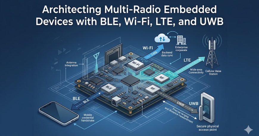
Choosing BLE plus Wi-Fi plus UWB means choosing a chipset (or combination of chipsets) that supports that exact set, an antenna configuration that gives each radio enough isolation to not desensitize the others, a power budget that assumes certain radios are off most of the time, and a certification path that covers every one of those radios in every region the product ships to.
Each of those downstream decisions assumes the radio set is fixed. If a customer asks six months into development for UWB ranging that wasn’t in the original spec, the answer usually isn’t “we’ll add a UWB chip.” It’s closer to “we need a new board revision, a new antenna layout, a new RF coexistence study, and a new certification cycle” — months of work triggered by a requirement that, on paper, looks like adding one part to a BOM.
The reverse is just as costly. Overprovisioning — adding LTE “just in case,” or UWB because a competitor’s spec sheet has it, means paying for certification, power budget, and board space for a radio that may never get used. On a product shipping in volume, that’s not a rounding error; it’s margin, gone, on every unit, for the life of the product.
Once the product features are clear, the next step is to match each feature to the radio that solves it, and resist the temptation to make one radio do a job it wasn’t built for. Each of these technologies has a narrow zone (sweet spot) where it’s the ideal answer, a much wider zone where it’s just ok, and a wide zone where it’s the wrong choice.
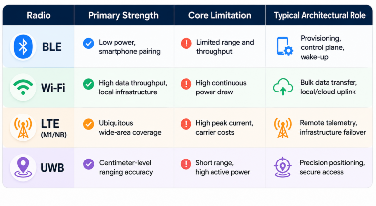
BLE is the default for short-range, low-power interaction between a device and a phone. It’s good at presence detection in a loose sense, pairing, small data exchanges, and running for years on a coin cell.
What it’s not good at is precision. BLE signal strength (RSSI) can tell you roughly whether something is near or far, but “roughly” can mean several meters of error depending on the environment. A closed door, a person’s body, a metal cabinet can all shift the reading enough to make an access-control decision unreliable. BLE answers “is a known device: somewhere nearby vs at this specific point in space.”
UWB exists for the question BLE can’t answer: precise distance and, with the right setup, direction. Using time-of-flight measurements across a wide spectrum band, UWB can resolve position to within centimeters, largely independent of the interference and multipath issues that make BLE’s RSSI unreliable indoors.
This is why it has become the standard for secure ranging, proving a credential is physically at the door, not just somewhere in the building. It is used for spatial awareness use cases like asset tracking or hands-free unlock.
The tradeoff is power and cost. UWB radios draw more current than BLE and add bill-of-material cost, so they show up only when the product genuinely needs spatial precision, not as a general-purpose connectivity radio.
Wi-Fi is the high-bandwidth, infrastructure-dependent option. It’s the right choice when a device needs to move real data, such as firmware updates, video, logs, large configuration syncs, and when it can rely on existing network infrastructure being present and powered.
Wi-Fi’s weaknesses are exactly its dependencies: it needs an access point in range, it draws meaningfully more power than BLE (especially when maintaining an active connection), and it inherits whatever reliability problems exist on the local network. A device that only has Wi-Fi has no story for “what happens when the network is down,” which is precisely the gap LTE fills.
LTE (or cellular more broadly) is the answer to “this device needs to reach the outside world regardless of what local infrastructure does or doesn’t exist.” It doesn’t depend on a router, a switch, or anyone’s IT configuration. It depends on a SIM and a cell tower. That independence is also its cost.
Cellular modules are more expensive, carry recurring data plan costs, and consume more power than any of the other three radios discussed here. LTE earns its place on a board when a device going silent because someone unplugged a switch is unacceptable.
Thread is worth understanding separately from BLE and Wi-Fi, even though it often ships on the same combo silicon. It’s a low-power, IPv6-based mesh networking protocol built specifically for IoT devices. Where BLE connects a device to a phone and Wi-Fi connects it to the internet, Thread connects groups of devices to each other and to a border router, forming a self-healing mesh that doesn’t depend on a central access point staying online.
Its sweet spot is dense deployments of battery-powered nodes that need to communicate reliably without individually maintaining a Wi-Fi connection — think building sensors, industrial monitoring arrays, or smart lighting grids.
Many modern Wi-Fi combo chips from Silicon Labs, Nordic, and NXP already include Thread support alongside BLE, so the incremental BOM cost is often minimal. The decision is less about hardware and more about whether your application architecture can take advantage of the mesh.
Zigbee occupies similar territory to Thread — low power, mesh networking, short-range IoT — but with a longer installed base and deeper penetration in industrial and building automation markets. Where Thread is IP-native and designed with future interoperability in mind, Zigbee has decades of deployed infrastructure behind it, particularly in smart energy, HVAC, and industrial control environments where ripping out existing infrastructure is not an option.
Like Thread, Zigbee frequently ships bundled on combo chips alongside Wi-Fi and BLE. For products intended for environments where a Zigbee coordinator is already present or where the customer base expects Zigbee compatibility, it earns its place without adding significant BOM cost. For greenfield deployments with no existing Zigbee infrastructure, Thread’s IP-native architecture is generally the more future-proof choice.
There’s a lot more interesting comparisons and contrasts in our previous post – UWB vs BLE vs Wi-Fi for Indoor Location Tracking.
In practice, most multi-radio products fall into a handful of recognizable patterns, and which pattern fits depends less on what the radios do individually and more on how tightly they need to be coordinated. Here are four common multi radio approaches:
Many modern wireless SoCs bundle BLE and Wi-Fi (and sometimes Thread or Zigbee) into a single chip with shared RF front-end logic. This is the simplest path when the radio set aligns with what the SoC vendor offers: one part number, one toolchain, one set of drivers, and coexistence handled to varying degrees by the vendor’s firmware.
The constraint is that the product’s radio requirements must fit within what the SoC was designed to support. If the access controller needs UWB and the SoC doesn’t include it, this pattern stops being an option for that radio, no matter how convenient it is for the other two.
Here, a main application processor (often running Linux or a heavier RTOS) talks to separate modules for each radio it doesn’t have natively — a Wi-Fi/BLE combo module over SPI or UART, a UWB module over SPI, an LTE module over a serial AT-command interface.
This is the most flexible pattern and the one that scales best to four radios, because each module can be sourced, certified, and swapped somewhat independently. The cost is integration complexity: every module has its own driver and power sequencing requirements, and the host processor has to arbitrate between them — including managing which radios can be active at the same time without desensitizing each other.
In more constrained designs, a small microcontroller is dedicated solely to managing radios — handling BLE and UWB, for instance — while a separate, more capable processor handles the application logic and interfaces with Wi-Fi and LTE.
This splits the problem along power and real-time boundaries: the radio co-processor can stay in a low-power state managing BLE advertising or UWB ranging windows, while the main processor only wakes for higher-level tasks.
It adds a second processor and an inter-processor communication layer, but it can meaningfully reduce overall power draw in products where BLE or UWB need to be active far more often than Wi-Fi or LTE.
For products where LTE is the primary link and everything else is secondary — remote sensors with a BLE configuration interface, for example — the LTE module often becomes the de facto main processor, running application logic on its embedded MCU and treating BLE as a peripheral feature rather than a full radio stack.
This minimizes part count and cost but constrains how much local processing or radio coordination the product can do, since the cellular module’s MCU is typically far less capable than a dedicated application processor.
Picking the right radios and the right architecture pattern gets a design to the starting line. What happens when four radios have to share one board and operate at the same time is where most of the real engineering effort goes, and where most of the surprises show up late.
BLE, Wi-Fi, and parts of UWB all operate in or near the 2.4 GHz band, and when they’re on the same board, they interfere with each other. A Wi-Fi transmission can desensitize a BLE receiver sitting a few millimeters away on the same PCB, causing dropped connections or missed packets that have nothing to do with either radio’s actual range.
Solving this isn’t a matter of picking good chips; it requires coexistence schemes — time-division arbitration between radios, frequency planning, and sometimes dedicated coexistence signaling lines between chips — that have to be designed in from the start and validated with real RF measurements.
Four radios usually means four antennas (or, at minimum, several), and on a small board there often isn’t a clean way to place them all without some degree of mutual coupling. An antenna tuned for UWB’s wide bandwidth has different placement and ground-plane requirements than a BLE antenna, and putting them too close together degrades both.
This is one of the reasons radio decisions can’t be deferred. Antenna placement is decided at board layout, and a layout designed for three antennas doesn’t have a clean path to “just add a fourth” without redoing the RF design around it.
Each radio has a different power profile, and the difference between “available” and “active” matters enormously. UWB ranging and active Wi-Fi connections can draw an order of magnitude more current than BLE in a low-power advertising state.
A device that needs to run on battery for months, but also needs to maintain a UWB ranging session for security, has to carefully duty-cycle which radios are active when — UWB only during the ranging window, Wi-Fi only during sync windows, LTE only as a fallback — and the firmware managing that duty cycling has to be correct, because a bug that leaves one radio on continuously can turn a multi-month battery life into a multi-day one.
Every radio on the board needs regulatory certification, such as FCC and CE, for every region the product ships to, and these certifications aren’t independent of each other. Adding a radio, or even changing antenna placement for an existing one, can require recertifying the whole RF system.
For a product shipping to multiple regions, this multiplies: four radios across, say, North America, Europe, and a few other markets can mean a dozen or more separate certification efforts, each with its own timeline and cost, and each one that has to be redone if the RF design changes after the fact.
The application layer generally shouldn’t need to know whether a connection came over Wi-Fi or LTE, or whether a presence signal came from BLE or UWB. But someone has to build that abstraction, and it has to handle radios with very different connection models, latencies, and failure modes underneath a single interface.
Getting this wrong creates products where switching between radios (say, falling back from Wi-Fi to LTE when the network drops) introduces visible delays, dropped data, or inconsistent behavior that the end user experiences as the product simply being unreliable.
None of these is a separate workstream that can be solved in isolation and then assembled; they have to be reasoned about together, from early in the design, by people who understand how each piece constrains the others
A few trends are starting to reshape how these tradeoffs get made, and most of them point toward pushing more of the multi-radio complexity off the board designer’s plate and into silicon, software stacks, and standards that didn’t exist a few years ago.
The first wave of combo chips merged BLE and Wi-Fi because they were the most common pairing and shared enough RF infrastructure to make integration worthwhile. The newer wave is starting to add UWB into that mix, and a few vendors are exploring tighter integration with cellular as well.
As this continues, some of the products described earlier, like the access controller that needs BLE, UWB, Wi-Fi, and LTE, may eventually be built around two chips instead of four, with much of the coexistence work handled inside the combo part rather than designed from scratch on the board.
Coexistence between radios was something board designers solved after the fact — adding coexistence signaling lines between separately-sourced chips, tuning time-division schedules in firmware.
Newer silicon is starting to build coexistence arbitration in as a designed feature, with chips that are aware of each other’s activity and negotiate airtime automatically rather than requiring a board-level protocol to be designed and validated independently for each combination of parts.
UWB’s role was usually kept as a radio added only when a product specifically needed that capability. As UWB chips get cheaper and smaller, and as ecosystems (particularly around digital car keys and access control) standardize on UWB for proximity verification, it’s increasingly showing up as a default inclusion in certain product categories. This shifts UWB from “the radio you add if you need precise ranging” toward “the radio you include by default in this category, the way BLE became default a decade ago.”
The idea of a connectivity manager — a software layer that gives the application a single “connected/disconnected” interface regardless of which radio underneath provides it — isn’t new, but until recently most of these were built in-house, per product, with all the inconsistency that implies.
Some RTOS vendors and silicon vendors are starting to ship more complete connectivity stacks as part of their SDKs, covering radio selection, fallback logic, and power state management together. This is reducing the amount of glue code a multi-radio product needs to write from scratch.
BLE, Wi-Fi, LTE, and UWB modules are well-documented, widely sourced, and individually well understood. What’s hard is the part that doesn’t show up on any single chip’s datasheet: how they behave once they’re sharing a board, a power budget, and an antenna layout — and how that combination holds up across years of firmware updates and certification cycles in the field.
That’s the gap between a product that works in a lab demo and one that works on a loading dock in winter, on a battery that has to last a year, and on a network connection that drops without warning. Closing that gap isn’t a single decision. It’s dozens of smaller ones, made early, by people who’ve seen where these designs tend to go wrong before they go wrong.
This is the kind of problem embedUR works on with clients — taking a product from “here’s what it needs to do” to a board and firmware architecture that holds up once it’s shipped, across the radios, the power budget, and the years of updates that follow.
If you’re working through a multi-radio architecture decision and want a second set of eyes before it’s locked into silicon, talk to embedUR’s connectivity team. The earlier this conversation happens, the more options stay open.
Put BLE and Wi-Fi on the same board, run them both under load, and something often happens that no bench test predicted. BLE connections start dropping. Not randomly, and not because either radio has a defect. They drop specifically during Wi-Fi bulk transfers, OTA updates, large telemetry syncs, and video uploads, and they recover once the Wi-Fi traffic quiets down.
This is RF coexistence, and it is one of the most consistently under-planned aspects of multi-radio embedded design. Not because engineers don’t know about it, but because it almost never surfaces in a lab environment. We’ve covered more on this in a previous post – UWB vs BLE vs Wi-Fi.
Basically, labs don’t generate the kind of sustained, simultaneous radio demand that a product sees in actual use. So the problem ships, and it gets diagnosed from field reports rather than from a test pass.
For most of embedded hardware’s history, putting multiple radios on one board was a specialized design decision, something that gateway and hub teams dealt with. Ordinary products carried one radio, and there was nothing to arbitrate.
That has changed. BLE combined with Wi-Fi is now close to a default configuration across consumer electronics, industrial IoT, and commercial connected hardware. In most of these designs, both radios live on a single combo chip with one shared RF front-end.
The shared front-end is what creates the coexistence problem, and it exists regardless of which vendor’s silicon is on the board and regardless of how capable that silicon is.
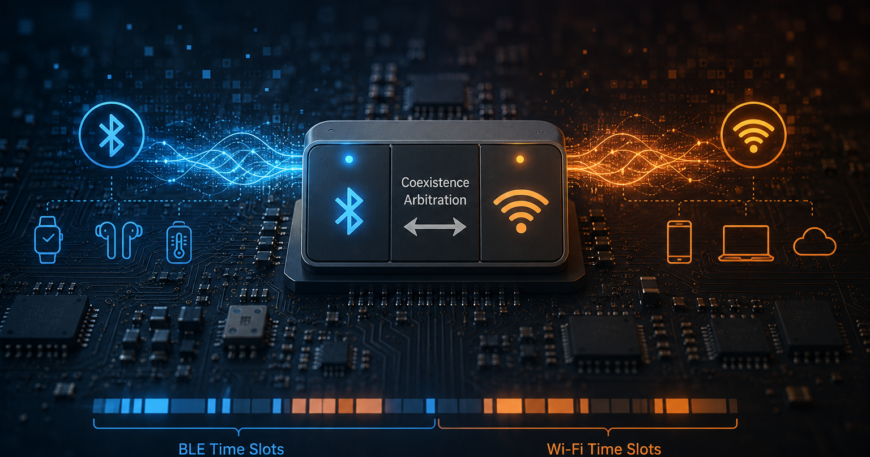
A combo chip with BLE and Wi-Fi does not let both radios transmit at the same time. An arbitration layer sits between the two radio stacks and the shared hardware, deciding on a millisecond timescale which radio gets access to the front-end at any given moment.
The diagram below shows the full structure:
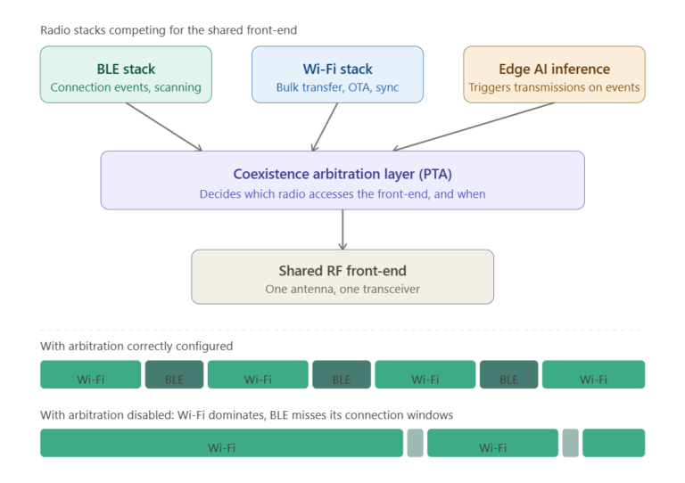
As Espressif’s ESP-IDF coexistence documentation describes, the allocation shifts across four defined states: idle, connected, scanning, and connecting, with each state carrying a different time-slice proportion between Wi-Fi and BLE.
When Wi-Fi is idle, BLE gets a generous slice. When Wi-Fi is actively transferring data, its slice expands and BLE’s contracts. The arbitration layer adjusts this continuously based on real-time conditions.
But the problem is that BLE has firm timing requirements at the protocol level. A BLE peripheral that misses its scheduled connection interval can be treated as disconnected by the central device, because the central has no way to distinguish between a missed packet and a dropped link.
Wi-Fi during a bulk transfer holds the front-end for longer continuous windows than BLE’s connection intervals can accommodate. When arbitration is not tuned to protect BLE’s timing, Wi-Fi takes precedence by default, and BLE pays for it, in dropped connections.
The symptom shows up in three recognizable ways in production. BLE connections drop during Wi-Fi OTA updates or large data syncs. Wi-Fi throughput falls noticeably when BLE begins scanning. And in some designs, the failures are intermittent enough that they only emerge under real sustained load, making them hard to reproduce in normal testing.
Solving coexistence has historically meant firmware work. Engineers enable Packet Traffic Arbitration between the BLE and Wi-Fi cores, adjust BLE scan windows and connection intervals to create gaps that Wi-Fi can use without disrupting BLE’s timing, and validate the results under a realistic combined load.
That approach still applies, but silicon vendors are increasingly building coexistence arbitration into hardware. NXP’s IW612 and IW623 parts both implement a central hardware Packet Traffic Arbiter that provides real-time arbitration between Wi-Fi and Bluetooth on a per-packet basis, with software algorithms available to tune its behavior. This is a meaningful shift in who carries the base responsibility for solving the problem.
The important practical detail is that enabling this hardware capability is not automatic. NXP’s own application note states that the hardware PTA arbitration can be statically enabled or disabled. Espressif’s documentation for the ESP32-C3 explicitly states that coexistence must be enabled through menuconfig, otherwise the coexistence function cannot be used.
A team that integrates one of these chips, validates it in a quiet RF environment, and ships without configuring the coexistence hardware is shipping a product that has the capability to manage the problem correctly, but is not using it.
This is the most common source of coexistence failures on modern silicon. It is not a hardware limitation. It is a configuration step that did not happen.
On-device inference does not directly compete for radio time. Modern edge AI hardware is increasingly built around dedicated inference cores or micro-NPUs that run alongside the main MCU specifically to avoid that kind of contention. The inference workload itself does not draw on the radio front-end.
What draws on the radio is what the inference result decides to do. When a model detects an anomaly, recognizes a keyword, or crosses a threshold, it typically triggers a transmission: an alert over BLE, a compressed event clip over Wi-Fi, a status update over LTE. That transmission enters the same arbitration queue as every other radio event on the board.
Research on edge AI scheduling increasingly treats inference timing and radio access as a joint coordination problem, because separating them creates edge cases where an inference-triggered event competes poorly for radio time at exactly the moment when timely delivery matters most.
For teams designing a coexistence policy, this is worth planning for. A policy tuned around predictable periodic telemetry and scheduled OTA windows will behave differently once an inference layer adds an event-driven, unpredictable source of radio demand. The arbitration parameters that work well in one traffic model may not hold in the other.
Coexistence problems found early are configuration problems. Coexistence problems found after a board is finalized are much harder to resolve cleanly. Firmware workarounds can reduce the severity, usually by sacrificing some performance on one radio to protect the other.
If the antenna layout does not provide adequate physical isolation between the two radio paths, firmware tuning alone may not be sufficient, and the fix requires a board revision with the associated schedule and recertification cost.
The teams that ship clean multi-radio products tend to follow a few practices that are not complicated but are easy to skip under schedule pressure.
1. They read the coexistence section of the vendor SDK documentation before bring-up, not during debugging. Every major combo silicon vendor, including Espressif, Silicon Labs, Nordic, and NXP, publishes application notes and SDK configuration guides specifically for coexistence.
These documents describe which registers to enable, which parameters to tune, and which traffic scenarios to validate against. Most of the configuration that teams discover they needed during field escalations was already documented before the product shipped.
2. They configure the coexistence hardware explicitly, rather than leaving it at SDK defaults. As discussed earlier, most vendor SDKs do not enable coexistence arbitration by default. Treating a default configuration as a validated configuration is where most avoidable coexistence problems begin.
3. They test under simultaneous, sustained load before the board is locked. This means running a BLE connection and a Wi-Fi bulk transfer at the same time, at the data rates and packet sizes the product will actually see in the field, not in isolation on a quiet bench. A spectrum analyzer during this test is not optional. It is what makes the arbitration behavior visible rather than inferred from symptoms.
4. They account for event-driven radio demand if the product includes any form of on-device inference. A model that triggers transmissions changes the traffic profile the arbitration system has to manage. Teams that model only their periodic telemetry and OTA traffic when tuning coexistence parameters, and then add inference later, often find that the parameters need revisiting.
5. They treat coexistence validation as a gate in the design process, not a checkbox after the fact. The engineers who avoid field escalations are not necessarily more skilled than the ones who don’t. They are more deliberate about when in the schedule this validation happens.
RF coexistence is not an exotic problem, but it’s one that’s hard to avoid these days with multi-radio chips increasingly becoming the norm. It is a predictable consequence of putting multiple radios on shared silicon without a deliberate coordination strategy.
The tools to manage it are well documented, the silicon to handle it is widely available, and the validation process is straightforward. What it requires is that the work gets done at the right point in the design cycle, before the board is locked rather than after the product is in the field.
The products that handle this well are not the ones built by teams with access to better components. They are the ones built by teams who treated radio coordination as a critical design requirement from the beginning.
If your team is working through a coexistence problem on a current design, or planning a product that will combine radios on shared silicon for the first time, embedUR’s engineering team is happy to take a look.
We have worked through this class of problem dozens of times across BLE and Wi-Fi combo designs from several silicon vendors, and we can help identify where the gap is and what it takes to close it. Get in touch with us here.
Put BLE and Wi-Fi on the same board, run them both under load, and something often happens that no bench test predicted. BLE connections start dropping. Not randomly, and not because either radio has a defect. They drop specifically during Wi-Fi bulk transfers, OTA updates, large telemetry syncs, and video uploads, and they recover once the Wi-Fi traffic quiets down.
This is RF coexistence, and it is one of the most consistently under-planned aspects of multi-radio embedded design. Not because engineers don’t know about it, but because it almost never surfaces in a lab environment. We’ve covered more on this in a previous post – UWB vs BLE vs Wi-Fi.
Basically, labs don’t generate the kind of sustained, simultaneous radio demand that a product sees in actual use. So the problem ships, and it gets diagnosed from field reports rather than from a test pass.
For most of embedded hardware’s history, putting multiple radios on one board was a specialized design decision, something that gateway and hub teams dealt with. Ordinary products carried one radio, and there was nothing to arbitrate.
That has changed. BLE combined with Wi-Fi is now close to a default configuration across consumer electronics, industrial IoT, and commercial connected hardware. In most of these designs, both radios live on a single combo chip with one shared RF front-end.
The shared front-end is what creates the coexistence problem, and it exists regardless of which vendor’s silicon is on the board and regardless of how capable that silicon is.
A combo chip with BLE and Wi-Fi does not let both radios transmit at the same time. An arbitration layer sits between the two radio stacks and the shared hardware, deciding on a millisecond timescale which radio gets access to the front-end at any given moment.
The diagram below shows the full structure:
As Espressif’s ESP-IDF coexistence documentation describes, the allocation shifts across four defined states: idle, connected, scanning, and connecting, with each state carrying a different time-slice proportion between Wi-Fi and BLE.
When Wi-Fi is idle, BLE gets a generous slice. When Wi-Fi is actively transferring data, its slice expands and BLE’s contracts. The arbitration layer adjusts this continuously based on real-time conditions.
But the problem is that BLE has firm timing requirements at the protocol level. A BLE peripheral that misses its scheduled connection interval can be treated as disconnected by the central device, because the central has no way to distinguish between a missed packet and a dropped link.
Wi-Fi during a bulk transfer holds the front-end for longer continuous windows than BLE’s connection intervals can accommodate. When arbitration is not tuned to protect BLE’s timing, Wi-Fi takes precedence by default, and BLE pays for it, in dropped connections.
The symptom shows up in three recognizable ways in production. BLE connections drop during Wi-Fi OTA updates or large data syncs. Wi-Fi throughput falls noticeably when BLE begins scanning. And in some designs, the failures are intermittent enough that they only emerge under real sustained load, making them hard to reproduce in normal testing.
Solving coexistence has historically meant firmware work. Engineers enable Packet Traffic Arbitration between the BLE and Wi-Fi cores, adjust BLE scan windows and connection intervals to create gaps that Wi-Fi can use without disrupting BLE’s timing, and validate the results under a realistic combined load.
That approach still applies, but silicon vendors are increasingly building coexistence arbitration into hardware. NXP’s IW612 and IW623 parts both implement a central hardware Packet Traffic Arbiter that provides real-time arbitration between Wi-Fi and Bluetooth on a per-packet basis, with software algorithms available to tune its behavior. This is a meaningful shift in who carries the base responsibility for solving the problem.
The important practical detail is that enabling this hardware capability is not automatic. NXP’s own application note states that the hardware PTA arbitration can be statically enabled or disabled. Espressif’s documentation for the ESP32-C3 explicitly states that coexistence must be enabled through menuconfig, otherwise the coexistence function cannot be used.
A team that integrates one of these chips, validates it in a quiet RF environment, and ships without configuring the coexistence hardware is shipping a product that has the capability to manage the problem correctly, but is not using it.
This is the most common source of coexistence failures on modern silicon. It is not a hardware limitation. It is a configuration step that did not happen.
On-device inference does not directly compete for radio time. Modern edge AI hardware is increasingly built around dedicated inference cores or micro-NPUs that run alongside the main MCU specifically to avoid that kind of contention. The inference workload itself does not draw on the radio front-end.
What draws on the radio is what the inference result decides to do. When a model detects an anomaly, recognizes a keyword, or crosses a threshold, it typically triggers a transmission: an alert over BLE, a compressed event clip over Wi-Fi, a status update over LTE. That transmission enters the same arbitration queue as every other radio event on the board.
Research on edge AI scheduling increasingly treats inference timing and radio access as a joint coordination problem, because separating them creates edge cases where an inference-triggered event competes poorly for radio time at exactly the moment when timely delivery matters most.
For teams designing a coexistence policy, this is worth planning for. A policy tuned around predictable periodic telemetry and scheduled OTA windows will behave differently once an inference layer adds an event-driven, unpredictable source of radio demand. The arbitration parameters that work well in one traffic model may not hold in the other.
Coexistence problems found early are configuration problems. Coexistence problems found after a board is finalized are much harder to resolve cleanly. Firmware workarounds can reduce the severity, usually by sacrificing some performance on one radio to protect the other.
If the antenna layout does not provide adequate physical isolation between the two radio paths, firmware tuning alone may not be sufficient, and the fix requires a board revision with the associated schedule and recertification cost.
The teams that ship clean multi-radio products tend to follow a few practices that are not complicated but are easy to skip under schedule pressure.
1. They read the coexistence section of the vendor SDK documentation before bring-up, not during debugging. Every major combo silicon vendor, including Espressif, Silicon Labs, Nordic, and NXP, publishes application notes and SDK configuration guides specifically for coexistence.
These documents describe which registers to enable, which parameters to tune, and which traffic scenarios to validate against. Most of the configuration that teams discover they needed during field escalations was already documented before the product shipped.
2. They configure the coexistence hardware explicitly, rather than leaving it at SDK defaults. As discussed earlier, most vendor SDKs do not enable coexistence arbitration by default. Treating a default configuration as a validated configuration is where most avoidable coexistence problems begin.
3. They test under simultaneous, sustained load before the board is locked. This means running a BLE connection and a Wi-Fi bulk transfer at the same time, at the data rates and packet sizes the product will actually see in the field, not in isolation on a quiet bench. A spectrum analyzer during this test is not optional. It is what makes the arbitration behavior visible rather than inferred from symptoms.
4. They account for event-driven radio demand if the product includes any form of on-device inference. A model that triggers transmissions changes the traffic profile the arbitration system has to manage. Teams that model only their periodic telemetry and OTA traffic when tuning coexistence parameters, and then add inference later, often find that the parameters need revisiting.
5. They treat coexistence validation as a gate in the design process, not a checkbox after the fact. The engineers who avoid field escalations are not necessarily more skilled than the ones who don’t. They are more deliberate about when in the schedule this validation happens.
RF coexistence is not an exotic problem, but it’s one that’s hard to avoid these days with multi-radio chips increasingly becoming the norm. It is a predictable consequence of putting multiple radios on shared silicon without a deliberate coordination strategy.
The tools to manage it are well documented, the silicon to handle it is widely available, and the validation process is straightforward. What it requires is that the work gets done at the right point in the design cycle, before the board is locked rather than after the product is in the field.
The products that handle this well are not the ones built by teams with access to better components. They are the ones built by teams who treated radio coordination as a critical design requirement from the beginning.
If your team is working through a coexistence problem on a current design, or planning a product that will combine radios on shared silicon for the first time, embedUR’s engineering team is happy to take a look.
We have worked through this class of problem dozens of times across BLE and Wi-Fi combo designs from several silicon vendors, and we can help identify where the gap is and what it takes to close it. Get in touch with us here.
Measuring where a person or object is with Bluetooth Low Energy (BLE) is like finding a bakery by its smell. You know it is close, you just can’t tell if it is 10 metres ahead or 30 metres to your left. Ultra-Wideband (UWB) gives you an edge. It measures the same distance the way a tape measure does: accurate to the centimetre. That precision is why UWB is showing up in applications where BLE cannot deliver. Every one of those applications is a firmware team solving a problem BLE never forced them to think about.
Most of the content written about UWB fixates on Real-Time Location Systems (RTLS: infrastructure-heavy tracking systems that monitor the positions of assets and people across a large space using fixed anchor hardware).
That coverage has its place. However, the five applications where firmware teams are doing the most interesting work “right now” go largely unwritten about: autonomous robot follow-me, child presence detection tied to automotive safety ratings, gesture recognition without cameras, contactless vital sign monitoring, and peer-to-peer ranging in consumer devices. Two of these are what regulation mandates. But all five are firmware-intensive in ways warehouse tracking never is.
This article covers all five. It includes: why UWB fits each problem, what the firmware actually has to do, and which silicon fits each use case. As for the alternatives, catch a more detailed read in our other post – UWB vs BLE vs Wi-Fi: A Firmware Engineer’s Decision Framework.
A UWB pulse lasts less than one nanosecond, the time it takes light to travel roughly 30 centimetres. That timing precision is what makes UWB a ruler rather than a radio.
Here is what “wide frequency bandwidth” means in plain terms. Narrow-band radios broadcast the way someone holds a long note on a saxophone: by the time the note reaches you directly, the echo bouncing off the wall is already on top of it.
The two blur into one sound. UWB broadcasts the way a drummer plays a single sharp hit: direct sound and echo arrive as two distinct beats you can tell apart. Spreading across 500 MHz gives the receiver that sharp-beat resolution. It separates the direct signal from its wall-reflected copies cleanly.
For firmware engineers, this shifts the problem from filtering and estimating to measuring and acting.
The five applications below all exploit that shift in different ways.
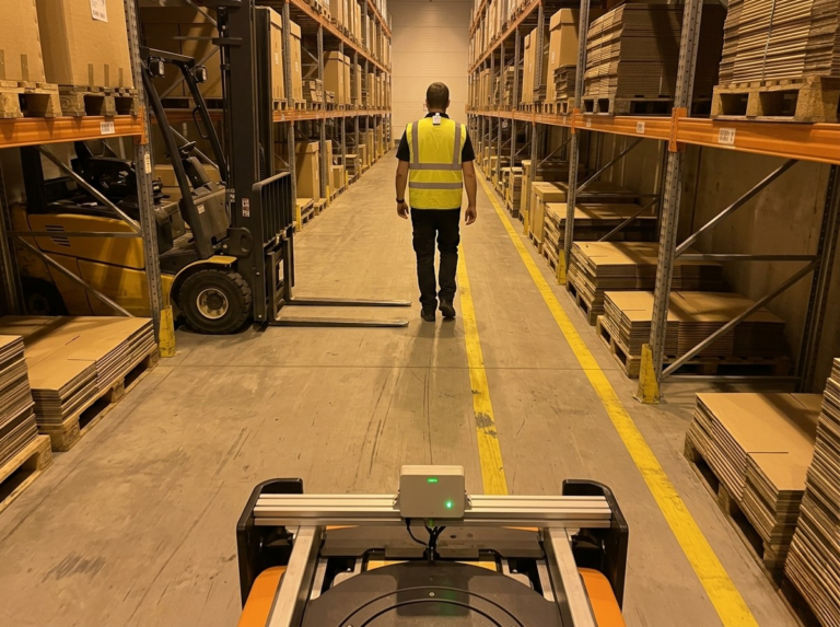
An autonomous follow-me robot is a wheeled or legged machine that follows a specific person through a shared workspace: a nurse down a hospital corridor, a warehouse picker between aisles, a logistics worker on a factory floor. The robot carries the tools, parts, or load the person would otherwise push on a cart. The design brief sounds simple. Stay a fixed distance behind the person. Close enough to be useful. Far enough to be safe. Never hit them.
The environment is where the job gets hard. For instance, in situations where: another person steps between the robot and the operator or the operator turns around and walks back to grab something from the cart. The robot has to spot the reversal, stop and hold its ground, then swing around and start following again once the operator heads off.
KUKA’s KMR iiwa, one of the most capable mobile robots on factory floors today, uses laser scanners to navigate for exactly these reasons. The same problem now shows up in humanoid robotics. Unitree’s G1 humanoid is already being paired with UWB tracking modules from vendors like Weston Robot. Once a humanoid is meant to share spaces with people, the robot must know the exact position of the person it follows, within a few centimetres, at all times.
BLE Received Signal Strength Indicator (RSSI) fails in these conditions because signal strength is a guess. The same received power could mean the operator is 2 metres directly ahead, or 8 metres away behind a steel shelf. UWB works differently. It timestamps when a radio signal is sent and when it comes back, divides by the speed of light, and returns a distance accurate to centimetres.
Think of it the way a ship uses sonar: send a pulse toward the seabed, wait for it to return, measure the round-trip time, and the depth is calculable to within metres.
TWR does the same thing between two UWB radios, at the speed of light: the tag sends a timestamped message, the anchor responds with its own timestamp, and the round-trip time reveals a distance accurate to centimetres. A UWB tag worn by the operator and an anchor node mounted on the robot exchange these ranging messages on a timed schedule.
The firmware on the robot side runs a ranging scheduler: a task that wakes the radio, collects the distance measurement, and passes it to the motion controller before putting the radio back to sleep. For heading estimation (knowing which direction to follow, in addition to how far), firmware teams typically fuse UWB readings from two or three tag positions with data from an Inertial Measurement Unit (IMU: a sensor that measures acceleration and rotation, used here to track which way the robot is turning).
Silicon that fits: the Qorvo DW3120 handles TWR with interrupt-driven firmware integration that maps cleanly onto a Real-Time Operating System (RTOS: the software layer that manages when each firmware task runs on the processor). For battery-operated operator tags where current draw is the binding constraint, Spark Microsystems documents the SR1000 at sub-mW active receive current at 0.85 Mbps in its product documentation.
For teams evaluating autonomous mobility systems: UWB follow-me removes the “clean environment” assumption from your testing checklist. The system works where your robot actually operates.

By 2026, Child Presence Detection (CPD) has become a requirement for top safety ratings in major markets, led by the European New Car Assessment Programme (Euro NCAP: the body that rates vehicle safety across Europe). Euro NCAP started awarding CPD points in 2023. From January 2025, the system must also detect a child aged three to six who climbs into an unlocked car on their own and becomes trapped when it locks. The US Hot Cars Act pushes a parallel regulatory path.
Two standards bodies carve up the CPD problem between them: Euro NCAP sets the detection requirements (what the system must spot, and how reliably), while the FiRa Consortium (Fine Ranging Consortium: the industry body that governs how UWB devices from different vendors talk to each other) sets the interoperability rules for the UWB radios themselves. For automotive suppliers and Tier 1 integrators, Euro NCAP’s CPD requirement is already scoring your competitors. This is an engineering deadline with a date attached, and a 5-star rating on the line.
The challenge is physical. A sleeping infant’s chest rises and falls three to eight millimetres with each breath. A heartbeat moves the chest by 0.2 to 0.5 millimetres. Cameras need good lighting and a clear view of the child. A closed car on a hot day gives you neither.
Think of UWB in-cabin sensing the way a bat navigates a cave. A bat reads the echo of its own chirp to map everything around it: walls, gaps, moving prey, without needing to see any of it.
A UWB radar node reads the echo of its own pulse, and a breathing chest changes that echo in a pattern no inanimate object in the car produces. The firmware configures the radio in radar mode rather than ranging mode, collects pulse-return data at a high repetition rate, applies signal averaging to filter out road vibration, and extracts the respiration waveform from what remains.The FiRa Consortium sets the interoperability rules for UWB ranging. The CPD sensing requirements (what the system must detect and how reliably) are governed by Euro NCAP.
Silicon that fits: NXP’s Trimension is the company’s family of UWB chips — the same line BMW uses for its Digital Key Plus passive entry system. NXP’s published documentation for in-cabin UWB sensing covers the Trimension CPD configuration in detail. The chip built for this job in production vehicles is the NCJ29D6A. It combines UWB ranging with short-range radar on a single chip and carries AEC-Q100 qualification (Automotive Electronics Council standard 100: the industry test suite that confirms a chip survives the temperature swings, vibration, and humidity a car endures over its lifetime). For CPD specifically, that matters because the chip has to keep working in a parked car that hits 70°C on a hot afternoon.
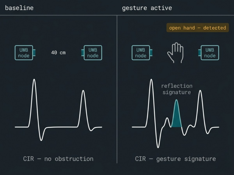
For product teams in automotive, consumer electronics, and industrial control: UWB gesture recognition works in any lighting condition, captures no image data, and runs five to seven recognised gestures at above 90% accuracy in production conditions. The privacy compliance burden disappears before it reaches your legal team.
Camera-based gesture systems face three challenges firmware teams rarely budget for up front. The first is the privacy compliance burden image capture brings with it. The second is processing demand most embedded platforms cannot spare. The third is a hard dependency on lighting conditions. UWB sidesteps all three.
Every UWB transmission channel produces a Channel Impulse Response (CIR). Think of the CIR the way a musician reads a room. Strike the same chord in an empty warehouse and in a tiled bathroom, and the note sounds different: same source, but completely different reflection profile.
When a hand moves between two UWB nodes, the CIR shifts in a pattern that matches the gesture. The firmware grabs the CIR frames at a fast update rate, hands them to a machine learning model running on the main microcontroller, and outputs the gesture in under 50 milliseconds.
How many gestures can UWB tell apart? A 2020 study hit 95% accuracy across eight hand gestures. The gestures were four swipe directions (left-right, right-left, up-down, down-up), two diagonal swipes, and two rotations (clockwise and counterclockwise). A 2021 public dataset stretched the count to twelve. In production cars, where a false positive is dangerous, vendors keep the menu tighter: five to seven gestures, accuracy above 90% once the model is trained on the actual cabin layout.
The implementation challenge is throughput. Raw CIR data coming off the radio must move to the classifier without stalling other firmware tasks. On an RTOS, that means a dedicated high-priority interrupt service routine handing data to a processing queue, with the classifier running as a lower-priority task against a timestamp-matched buffer. Teams that underestimate this pipeline are the ones who end up with gesture latency measured in seconds rather than milliseconds.
Silicon that fits: Where most ranging chips hand you a distance and nothing else, Qorvo DW3220 gives you the full raw reflection data directly. That full reflection fingerprint is what the classifier trains on and runs against. A mature driver ecosystem means the radio is up and feeding data quickly. The firmware problem left to solve is the interesting one: building the model.
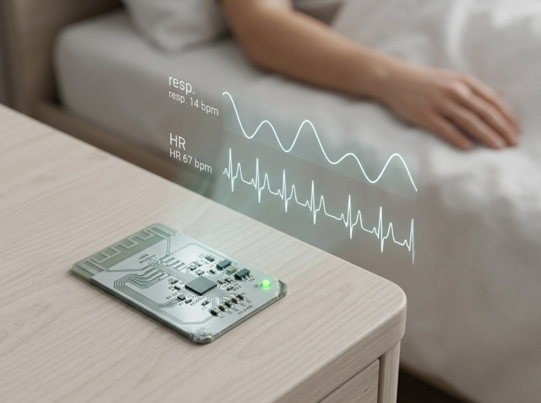
For medical device teams and automotive OEMs: contactless vital sign monitoring removes the need for electrodes, adhesives, or patient compliance. The sensor reads breathing and heartbeat at up to five metres of clear line-of-sight. It works whether the patient cooperates or not.
UWB can detect breathing and heartbeat through air, without touching the patient. The physics is the same impulse-radar principle used in contactless monitors in neonatal intensive care units (NICUs), where it has been tested against ECG and chest-impedance sensors on more than thirty premature babies in published clinical studies. Microwave radar has been used to monitor vital signs in clinics since the mid-1970s. UWB takes the same physics and shrinks it to fit the power budget and board space embedded engineers work with.
Each UWB pulse reflects off the chest wall. As the chest moves with each breath, the return time of the reflected pulse shifts by picoseconds (trillionths of a second), corresponding to a displacement of millimetres. The firmware averages thousands of pulse returns to pull this signal out of noise, applies bandpass filters tuned to the frequencies of human respiration (12 to 20 cycles per minute) and heartbeat (60 to 100 beats per minute), and produces a clean waveform a host processor can interpret.
A useful frame for picturing this: press your wrist gently against a drumhead while someone taps the other side of the drum. You feel the vibration clearly, even though your wrist is nowhere near the source. UWB reads the equivalent of that vibration through open air, without any physical connection to the patient. Working range for reliable respiration detection is up to approximately 5 metres under clear line-of-sight conditions.
Applications include neonatal monitoring, in-vehicle occupant detection as a complement to the CPD use case above, and eldercare systems where reducing physical contact with a sensor matters. A patient who moves or removes a wired monitor in the night still has a chest wall that can be monitored.
Silicon that fits: Novelda’s X4M200 is a dedicated Impulse-Radio UWB (IR-UWB: the sub-category of UWB that uses short, repeated radar-like pulses specifically for sensing rather than communication) respiration sensor. Novelda’s own product documentation confirms its 0.4 to 5-metre sensing zone for breathing detection, and the IR-UWB approach it uses is independently validated in peer-reviewed literature.
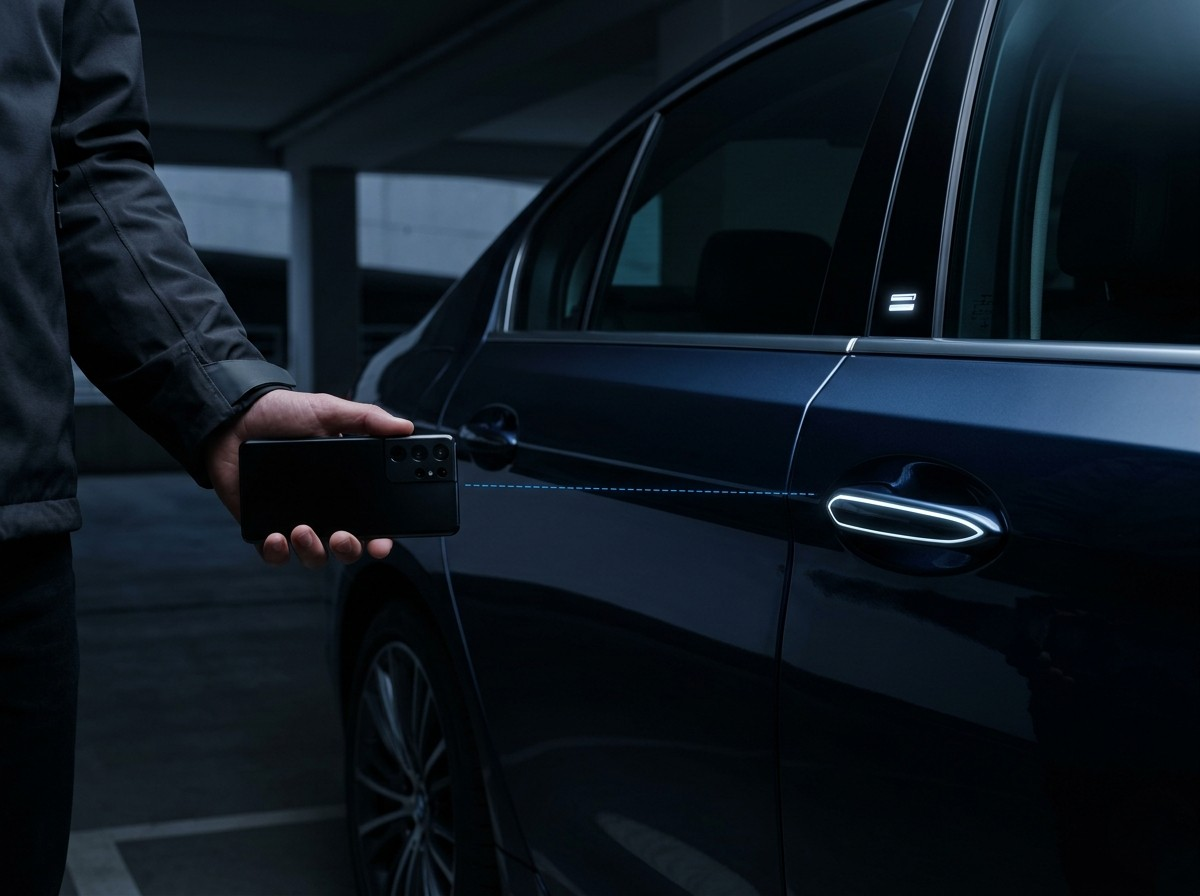
Fixed-infrastructure positioning is expensive. RTLS forces you to mount anchors on ceilings, calibrate them, run a location engine on a server, and pay to keep all of it running. That cost shuts a lot of useful applications out of the market.
Peer-to-peer (P2P) UWB ranging removes the infrastructure entirely. Two devices with UWB radios trade timestamped messages and work out the distance between them directly. No anchors. No server.
What this unlocks: Apple’s AirTag uses P2P UWB to point you to a misplaced wallet within a few centimetres. BMW’s Digital Key Plus uses it for hands-free entry: the owner’s phone ranges against a UWB node inside the car door, and the lock opens when the phone is authenticated and inside the permitted zone.
The Car Connectivity Consortium (CCC: the industry body that sets the standard for how phones unlock cars) defines this in its Digital Key 3.0 standard, covering both the ranging protocol and the security on top of it. Industrial proximity warning, asset pairing without a network, and contactless payment confirmation are all live build areas.
What firmware has to solve: The hard problem is not ranging. It is scheduling. When dozens of P2P devices range at the same time in a tight space like a car park, a warehouse loading dock, or a busy office, the protocol has to decide who talks when. If it gets that wrong, measurement collisions stack up into delays.
Think of P2P ranging like two people standing at opposite ends of a street, each holding a stopwatch synchronised to the same clock. One calls out, the other records the time of arrival and calls back. From those two timestamps and the known speed of radio waves, both can calculate the distance between them to within centimetres.
The firmware manages two roles: initiator (the device that sends the first ranging message) and responder (the device that timestamps receipt and replies). At product scale, the hard firmware problem shifts from ranging to scheduling: when dozens of P2P devices are ranging simultaneously in a confined space, the protocol must handle contention without measurement collisions stacking up into delays.
Silicon that fits: Qorvo documents the DW3xxx series for consumer and industrial P2P ranging in its “UWB in Digital Car Key” whitepaper, which details ranging performance in CCC Digital Key 3.0-compliant deployments. For automotive-grade implementations requiring both CCC compliance and AEC-Q100 qualification, NXP’s Trimension SR150 product documentation maps the chip directly to the CCC Digital Key 3.0 specification.

None of the five applications above uses ceiling anchors. None requires a cloud location engine. Strip away the RTLS framing that dominates most UWB content, and what remains is a single consistent capability: precise distance measurement between two points, executed in firmware, at close range.
That is the thread. Between two devices. Between a radar node and a chest wall. Between a robot and the operator it follows.
The firmware architecture that serves all five looks the same at its core: a ranging or radar engine producing raw measurements, a decision layer acting on those measurements against a threshold or model, and a power manager keeping the radio asleep between sessions. Master that pattern once, and it transfers across every application in this article.
One constraint carries across all five applications: line-of-sight matters, but the meaning is more specific than zero obstacles. Commercial UWB ranging chips operate in the 6 to 9 GHz band. At those frequencies the signal passes through drywall, wood, and glass with some loss of accuracy. It degrades sharply through brick and reinforced concrete. It is effectively blocked by metal: steel shelving, car door pillars, aluminium cabinets, copper plumbing in a wall. Water absorbs UWB too, which is why a human body itself blocks the signal.
The practical rule for firmware teams: a UWB node needs a clear radio path to its target, free of metal obstructions, with at least twenty centimetres of clearance from any nearby metal that could distort the antenna. A metal cabinet between a UWB node and a patient’s chest, a car door pillar between two ranging nodes, a steel shelf between a robot and its operator tag will all wreck measurement quality. Antenna placement is an architecture decision. Finalise it before the software stack takes shape.
The volume in UWB over the next product cycle is coming from these five firmware problems, driven by regulatory mandates, consumer product adoption, and the specific gap that centimetre-level ranging fills where BLE cannot.
Where does your current product sit against that list, and what does the firmware architecture need to look like when UWB joins the stack?
embedUR’s firmware team has integrated UWB ranging across automotive, consumer, and industrial applications. If you are evaluating UWB for any of the applications covered here, a 30-minute architecture review maps your requirements to a firmware topology and flags integration risks before any code is written.
If you enjoyed this article, discover even more of UWB’s capabilities in our next blog post – UWB Beyond Ranging: What IEEE 802.15.4ab Means for Your Firmware.
Too many times we’ve seen or heard a situation where a child falls asleep in the back seat. The driver steps away. Fifteen minutes later, the cabin temperature starts climbing. So, what if somewhere inside the dashboard, the same UWB chip that unlocked the car door when the driver approaches can do something entirely different. Like reading the faint reflections of its own radio pulses bouncing off the child’s chest, detecting the tiny rise and fall of breathing, and triggering an alert before heat becomes danger.
That capability will soon be available in modern production vehicles. The existing Ultra-Wideband (UWB) radio already inside the dashboard is learning a valuable second skill.
UWB has earned its place as the most accurate indoor positioning radio available, delivering centimeter-level distance measurements using time-of-flight (ToF): the time it takes a pulse to travel from one device to another and back. Our decision framework for indoor positioning radios covered the firmware realities of choosing between UWB, Bluetooth Low Energy (BLE), and Wi-Fi. That comparison assumed UWB was a ranging radio.
This article, which talks about the next-generation standard, IEEE 802.15.4ab, widens the assumption. With standardized radar sensing, a UWB anchor in a hospital hallway can detect whether an elderly patient has fallen, without a camera in the room. With 30x extended range, fewer anchors cover the same warehouse floor, cutting deployment costs and calibration overhead. Ranging is still there. Radar sensing, extended range, and 18x higher data rates now sit alongside it. For firmware teams, the radio’s job description just expanded, and the software has to keep up.

UWB ranging is a conversation between two devices. A tag sends a pulse, an anchor replies, and the system measures the round-trip time to calculate distance. Both sides participate.
UWB radar is an echo. One device sends pulses into a room and listens to what bounces back. No second device needed. The reflections carry information: where objects are, whether something is moving, and how far away it sits. What the device captures is called a channel impulse response, or CIR. Think of it as clapping once in an unfamiliar room. Every surface sends back an echo at a slightly different time and volume. A CIR is the full recording of all those echoes at once, preserving the timing and strength of each reflection path.
The physics underneath is the same as ranging: short pulses across a 500 MHz bandwidth. The difference is entirely in what the firmware does with the signal. Ranging firmware reads timestamps and computes distance. Radar firmware reads the CIR and runs detection algorithms: is something present? Is it moving? Is it breathing?
Two parameters control the trade-off. First, more samples per radar sweep extend the detection range from centimeters to several meters. Second, higher sweep rates improve accuracy but cost more power. Even at several meters of detection range, UWB radar draws under 10 milliwatts. That number keeps battery-powered devices on the table.
The practical result: a UWB anchor installed for digital key access can double as a presence sensor. Same hardware. No extra cost.

The current generation of UWB silicon, including Qorvo’s DW3xxx series and NXP’s Trimension platform, is built on IEEE 802.15.4z. That standard defined secure ranging and physical-layer (PHY) security: the lowest level of the radio hardware, where pulses are shaped and timed. It gave firmware teams a reliable foundation. Time-of-flight measurement with distance-bounding that prevents relay attacks (where a thief amplifies your car key signal from a distance to trick the lock into opening). Every production UWB ranging product on the market today runs on 802.15.4z.
IEEE 802.15.4ab is the successor, expected to be officially released in the first half of 2026. It is backward compatible with 802.15.4z, building on the existing foundation rather than discarding it. Going forward, three additions will matter for teams building on UWB:
1. Radar sensing becomes part of the standard: Under 802.15.4z, radar-like sensing was possible but vendor-specific. Qorvo published application notes on CIR-based presence detection using existing DW3xxx hardware. NXP shipped the Trimension SR250 with combined ranging and radar support. Each implementation used proprietary firmware interfaces. 802.15.4ab writes radar into the standard itself, defining how Impulse Radio UWB (IR-UWB) transceivers operate in sensing mode.
That means interoperable radar behavior across chipmakers. Not just interoperable ranging. Ceva is pushing this further: their Ceva-Waves UWB IP, the industry’s first 802.15.4ab-compliant design, supports combined ranging-and-radar sensing on a single silicon block. Because Ceva also licenses edge AI processors (NeuPro) and sensor fusion cores (MotionEngine), chipmakers can place the UWB radio and the radar detection algorithms on the same chip, rather than offloading CIR processing to a separate microcontroller.
For firmware engineers, this collapses two separate worlds into one. Today, your ranging code and your radar code (if you use it) talk to different vendor libraries with different data structures and different timing rules. A standardized radar mode means chipmakers will converge on common interfaces. Your architecture needs to anticipate a unified API (Application Programming Interface, the set of commands your code uses to control the chip) rather than two bolted-together SDKs (Software Development Kits).
2. Secure ranging pushes from pocket distance to building scale: Current 802.15.4z secure ranging works reliably at close proximity: digital keys, item finders, short-range access control. 802.15.4ab introduces multi-millisecond (MMS) ranging techniques. Instead of a single fast pulse exchange, MMS accumulates multiple measurements over a longer window, trading speed for signal gain. The result is more range at the same transmit power, and the early numbers suggest the gain is substantial.
How much more range are we talking about? Ceva’s 802.15.4ab-compliant UWB IP, announced on March 10, 2026, claims up to 30x range extension over current 802.15.4z. That moves UWB from “is the user next to the door?” to “where in this space are they?” UWB still works best within line-of-sight or through lightweight partitions, so “this space” means a floor, a warehouse zone, or an open facility rather than through concrete walls and steel framing. It pushes UWB into territory held by Wi-Fi Round-Trip Time (RTT) positioning and BLE Angle of Arrival (AoA), but with UWB’s inherent accuracy and security.
For firmware teams, longer-range sessions consume more energy per cycle, making your sleep and wake scheduling more consequential. Your power model has to account for these longer windows.
For decision-makers, the implication is simpler: UWB can now cover warehouse-scale and campus-scale spaces where teams previously had to fall back on BLE or Wi-Fi. Fewer compromises on accuracy, fewer radios to manage.
3. Data rates jump 18x: Current UWB devices communicate at 6.8 Megabits per second (Mbps). 802.15.4ab supports up to roughly 125 Mbps. That opens up use cases that pure ranging applications never needed: low-latency audio transport, richer protocol exchanges, and combined sessions where a single UWB transaction delivers both a position fix and a data payload.
For most Real-Time Location System (RTLS) and access control firmware, 6.8 Mbps has been more than enough. But if your product roadmap includes streaming sensor data alongside ranging, or pushing firmware updates over UWB rather than a separate BLE link, the additional bandwidth changes what your radio can carry.
In practice, you end up with one radio link that handles positioning, data transfer, and firmware updates. That is fewer radios in the design and fewer integration headaches in the field.
The volume signal underneath all of this: Grand View Research projects the global UWB market to grow at a CAGR of 18.9% from 2024 to 2030, reaching $4.37 billion by 2030 from an estimated $1.40 billion base in 2023. The ecosystem is moving. Also, Ceva’s announcement signals that compliant silicon IP is available for licensing now, meaning chipmakers can integrate it into next-generation Systems on Chip (SoCs: single chips combining processor, radio, and memory). Production parts built on 802.15.4ab are a design cycle away.
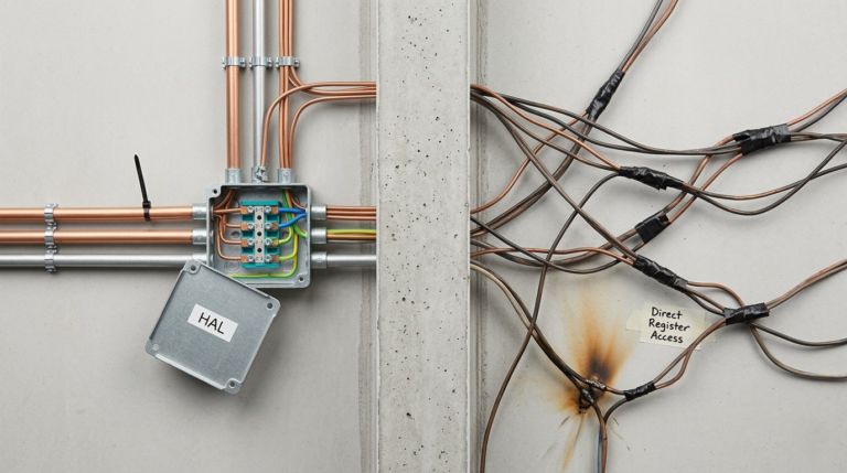
Here is where the standard meets the code your team writes.
a) Dual-mode scheduling: If your transceiver supports both ranging and radar, your Real-Time Operating System (RTOS: the software layer that decides when each task on the chip gets to run) has to manage two types of radio sessions with different timing profiles.
Think of it as air traffic control for a runway shared by two kinds of aircraft. Ranging sessions are the small fast jets: short bursts, tight timing, nanosecond-level precision. Radar sweeps are the heavy cargo planes: longer windows, more data collected, a different processing pipeline on the ground. Interleaving them without collision is a scheduling problem that ranging-only firmware never had to solve.
b) A new signal processing layer: Ranging firmware reads timestamps from the transceiver. Radar firmware reads CIR data: arrays of amplitude and phase samples that need filtering, thresholding, and classification to extract meaning (is someone present, are they moving, are they breathing). These are algorithmic problems that require more flash memory and RAM. If your current firmware barely fits in a DW3xxx’s companion microcontroller (MCU: the small processor running your tag’s software), radar processing will force a hardware reassessment.
c) Power budget complexity: A tag that ranges every 500 milliseconds has a predictable power profile. Add radar sweeps every 2 seconds and the profile shifts. Add adaptive logic that triggers radar only when ranging detects proximity, and the profile becomes state-dependent. Your power model needs to account for these layered modes. Otherwise, battery life estimates built for ranging alone will miss the mark.
d) The abstraction question: This one is about future-proofing. An abstraction layer in firmware works like a standard electrical outlet in a house. You plug in any appliance without rewiring the wall. Without that standard interface, every new device would mean tearing open the drywall. If your firmware talks directly to a 802.15.4z transceiver without a clean hardware abstraction layer between them, swapping in an 802.15.4ab chip later will mean rewriting that boundary. A few days of architecture work today prevents a quarter of rework after your product ships.
Automotive child presence detection: The European New Car Assessment Programme (Euro NCAP), the body that rates vehicle safety, have started tightening their scoring of vehicles on child presence detection (CPD) systems from 2025 onward. UWB radar detects micro-movements like breathing inside a cabin using the same anchor hardware as the digital key. No extra sensors. This is the first application where UWB radar will ship at volume, because regulation demands it.
Occupancy sensing without cameras: UWB radar detects presence and motion without capturing images. For healthcare facilities (fall detection in elder care), enterprise buildings (meeting room utilization), and smart buildings (heating, ventilation, and air conditioning automation), that privacy advantage changes the deployment conversation entirely.
Sparser infrastructure for indoor positioning: With 30x range improvement, fewer anchors cover the same floor space. Fewer anchors means lower deployment cost and less calibration overhead. Those two factors have been UWB’s most persistent adoption barriers.
If your team is mid-development on 802.15.4z, finish your product. The current silicon is stable and proven. But design your firmware with enough abstraction that the next chip does not demand a rewrite.
However, if you are in early product definition, factor in the widening value proposition. A radio that does ranging today and radar tomorrow carries a different cost-benefit weight than ranging alone.
Now, if your team is designing UWB firmware and wants to stress-test the architecture against what 802.15.4ab will demand, embedUR runs 30-minute architecture reviews. The review maps your requirements to firmware topology, models your power budget, and flags where your abstraction layer needs room to grow. That conversation costs less than the rework it prevents.
Which is cheaper for your team: the abstraction layer now, or the rewrite later?
In the embedded systems world, embedUR has spent the last twenty years in the trenches. We’ve built the wireless infrastructure that runs enterprise access points and the residential gateways sitting in millions of homes. In that time, we’ve learned one thing: regulatory shifts aren’t just legal problems. They are engineering problems.
The EU Cyber Resilience Act (CRA) is one of the biggest shifts we’ve seen in a decade. It isn’t just a footnote in a policy briefing; it’s a fundamental change in how we need to or should design, build, and most importantly, sustain products. At embedUR, we’ve guided teams through every Wi-Fi evolution from the early days of 802.11n to the complexities of Wi-Fi 6E and the new world of tinyML at the edge.
From where we stand, the CRA shouldn’t be a headache. It should be the catalyst that finally forces the industry to build smarter, more resilient systems.
But let’s be honest: for an engineering lead trying to hit a product launch date while staring down resource gaps, the CRA looks like a mountain of paperwork. To climb it, you have to bridge the gap between using an open-source RTOS like Zephyr and meeting the rigorous demands of European law.
We are currently in early 2026. The grace period is evaporating. The CRA was formally adopted back in late 2024, and the first major hammer will drop on September 11, 2026. That is the date when mandatory vulnerability reporting goes live.
If your device has a digital element and you sell it in the EU, you have 24 hours to report an exploited vulnerability. Not 24 hours after you fix it—24 hours after you find it.
By December 2027, the remaining requirements kick in: security-by-design as a legal mandate, machine-readable Software Bills of Materials (SBOMs), and a 5-year support window. If you miss these marks, the fines are eye-watering: up to €15 million or 2.5% of your global turnover. For any U.S. company exporting to Europe, which is a massive chunk of the global market, this is now the cost of doing business.
We’ve been working with Zephyr RTOS since its early releases in 2016. It’s under the Linux Foundation, it’s transparent, and it’s modular. On paper, it’s the perfect answer to the CRA.
Zephyr’s PSIRT (Product Security Incident Response Team) is excellent. They handle CVEs (Common Vulnerabilities and Exposures) with a level of transparency that mirrors the Linux kernel. When a bug is found in the networking stack, the fix is public and documented.
Furthermore, the Long-Term Support (LTS) releases, like the 3.7 LTS, offer five years of security maintenance. That perfectly maps to the CRA’s support requirements.
Zephyr also gives us the “West” tool. Using west spdx, we can generate an SBOM automatically during the build process. If you’ve ever tried to manually track every library and sub-component in a proprietary RTOS, you know that automated SBOM generation is a godsend. It takes the drudgery out of compliance.
However, this is the local engineer’s truth: upstream Zephyr is not the same thing as a shipping product.
Here is where the theory hits the floor. In our work sustaining Wi-Fi products for major global brands, where we manage fleets of over 10 million units, we’ve seen divergence as a major problem.
An engineer starts with a clean Zephyr LTS branch. Then, the silicon vendor provides a HAL (Hardware Abstraction Layer) that isn’t quite right for the specific power constraints of a Cortex-M4 gateway. So, the engineer tweaks the kernel. Then the marketing team requests a specific feature that requires a custom driver. Before you know it, you’ve forked the repo.
When a security patch comes down from the Zephyr upstream six months later, it doesn’t fit. It breaks your custom power management. It conflicts with your Wi-Fi driver. Now, compliance means a three-week rebase and a full regression test.
If you have a multi-SKU product line, maybe some devices use ARM and others use RISC-V, your vulnerability tracking turns into a nightmare. There are cases where a field-reported bug traced back to an unpatched erratum in a silicon vendor’s HAL. Because the team had drifted too far from the clean upstream code, they couldn’t pull the fix.
This kind of delay is exactly what the CRA will penalize.
The complexity doubles when you add tinyML. We’re seeing more industrial gear using TensorFlow Lite Micro on Zephyr to do predictive maintenance at the edge. These models are ultra-constrained. Every byte of RAM matters.
When you’re fighting for every kilobyte to make an AI model work on an IoT sensor, security overhead feels like an enemy. But under the CRA, that edge intelligence is part of the product’s digital footprint.
If your ML inference engine has a buffer overflow vulnerability, you are liable. Shoehorning these models into Zephyr while maintaining a secure, updatable bootloader (like MCUboot) requires a level of memory management that most teams aren’t prepared for.
So, how do we stop compliance from being a burden and turn it into a reason why customers choose you over a competitor? You have to treat security as a feature, not a chore.
The biggest mistake we see is that engineers treat Zephyr like a one-off download. You have to stay aligned with the LTS branches. We recommend a “cherry-pick” strategy. You pin your project to a stable LTS version and build a rigorous process for pulling in only the security patches you need. This keeps your custom “secret sauce” separate from the core RTOS plumbing.
If an auditor asks for your SBOM, you shouldn’t have to spend a week in Excel. We help our clients integrate SBOM tools directly into their CI/CD pipelines (like GitLab or GitHub Actions).
Every time a developer pushes code, the system should automatically run a vulnerability scan (using tools like grype or trivy) and generate a new SPDX file. If a vulnerability is found, the build should fail before the code ever reaches a device.
To handle the multi-SKU headache, we use Zephyr Device Tree overlays. Instead of having different codebases for different hardware, you keep one core application and use overlays to describe the hardware differences. This minimizes code drift and ensures that a security patch for your BLE stack works across every device in your catalog.
You can’t trust a simulation for CRA compliance. You need automated test rigs where real hardware is subjected to simulated exploits. At embedUR, we’ve built environments where we test everything from LTE stack vulnerabilities to timing glitches in crypto libraries.
This is how you catch a DoS (Denial of Service) bug before it gets found in the field and becomes a mandatory 24-hour report to the EU.
This is what we do. We aren’t a compliance consultancy that just hands you a PowerPoint. We are an engineering firm with over 400 expert embedded systems engineers who live in the kernel. Our architects have upstreamed code to Zephyr’s networking modules. We also know the silicon vendors—NXP, Infineon, Nordic, and Silicon Labs—and where their HALs usually break.
We have the sustainment framework ready to go. We handle the kernel upgrades, the CVE monitoring, and the SBOM maintenance so that your senior engineers can focus on the stuff that actually makes you money, like your next-gen predictive maintenance algorithms or your cloud-to-edge analytics.
The September 2026 deadline is closer than it looks on the calendar. In the world of embedded systems, eighteen months is one design cycle. If you start thinking about the CRA during the testing phase, you’ve already lost.
Is your Zephyr setup a solid foundation, or is it a house of cards? If you’re building for the EU market and worried about staying compliant without killing your product roadmap, let’s talk.
We can do a technical review of your current stack and show you exactly where the gaps are. We’ve been through the Wi-Fi wars and the IoT explosion; we can get you through this, too.
Let’s get your engineering team back to innovating. Schedule a Technical Review: Talk directly with our lead architects about your current Zephyr stack and CRA gaps.
In the embedded systems world, embedUR has spent the last twenty years in the trenches. We’ve built the wireless infrastructure that runs enterprise access points and the residential gateways sitting in millions of homes. In that time, we’ve learned one thing: regulatory shifts aren’t just legal problems. They are engineering problems.
The EU Cyber Resilience Act (CRA) is one of the biggest shifts we’ve seen in a decade. It isn’t just a footnote in a policy briefing; it’s a fundamental change in how we need to or should design, build, and most importantly, sustain products. At embedUR, we’ve guided teams through every Wi-Fi evolution from the early days of 802.11n to the complexities of Wi-Fi 6E and the new world of tinyML at the edge.
From where we stand, the CRA shouldn’t be a headache. It should be the catalyst that finally forces the industry to build smarter, more resilient systems.
But let’s be honest: for an engineering lead trying to hit a product launch date while staring down resource gaps, the CRA looks like a mountain of paperwork. To climb it, you have to bridge the gap between using an open-source RTOS like Zephyr and meeting the rigorous demands of European law.
We are currently in early 2026. The grace period is evaporating. The CRA was formally adopted back in late 2024, and the first major hammer will drop on September 11, 2026. That is the date when mandatory vulnerability reporting goes live.
If your device has a digital element and you sell it in the EU, you have 24 hours to report an exploited vulnerability. Not 24 hours after you fix it—24 hours after you find it.
By December 2027, the remaining requirements kick in: security-by-design as a legal mandate, machine-readable Software Bills of Materials (SBOMs), and a 5-year support window. If you miss these marks, the fines are eye-watering: up to €15 million or 2.5% of your global turnover. For any U.S. company exporting to Europe, which is a massive chunk of the global market, this is now the cost of doing business.
We’ve been working with Zephyr RTOS since its early releases in 2016. It’s under the Linux Foundation, it’s transparent, and it’s modular. On paper, it’s the perfect answer to the CRA.
Zephyr’s PSIRT (Product Security Incident Response Team) is excellent. They handle CVEs (Common Vulnerabilities and Exposures) with a level of transparency that mirrors the Linux kernel. When a bug is found in the networking stack, the fix is public and documented.
Furthermore, the Long-Term Support (LTS) releases, like the 3.7 LTS, offer five years of security maintenance. That perfectly maps to the CRA’s support requirements.
Zephyr also gives us the “West” tool. Using west spdx, we can generate an SBOM automatically during the build process. If you’ve ever tried to manually track every library and sub-component in a proprietary RTOS, you know that automated SBOM generation is a godsend. It takes the drudgery out of compliance.
However, this is the local engineer’s truth: upstream Zephyr is not the same thing as a shipping product.
Here is where the theory hits the floor. In our work sustaining Wi-Fi products for major global brands, where we manage fleets of over 10 million units, we’ve seen divergence as a major problem.
An engineer starts with a clean Zephyr LTS branch. Then, the silicon vendor provides a HAL (Hardware Abstraction Layer) that isn’t quite right for the specific power constraints of a Cortex-M4 gateway. So, the engineer tweaks the kernel. Then the marketing team requests a specific feature that requires a custom driver. Before you know it, you’ve forked the repo.
When a security patch comes down from the Zephyr upstream six months later, it doesn’t fit. It breaks your custom power management. It conflicts with your Wi-Fi driver. Now, compliance means a three-week rebase and a full regression test.
If you have a multi-SKU product line, maybe some devices use ARM and others use RISC-V, your vulnerability tracking turns into a nightmare. There are cases where a field-reported bug traced back to an unpatched erratum in a silicon vendor’s HAL. Because the team had drifted too far from the clean upstream code, they couldn’t pull the fix.
This kind of delay is exactly what the CRA will penalize.
The complexity doubles when you add tinyML. We’re seeing more industrial gear using TensorFlow Lite Micro on Zephyr to do predictive maintenance at the edge. These models are ultra-constrained. Every byte of RAM matters.
When you’re fighting for every kilobyte to make an AI model work on an IoT sensor, security overhead feels like an enemy. But under the CRA, that edge intelligence is part of the product’s digital footprint.
If your ML inference engine has a buffer overflow vulnerability, you are liable. Shoehorning these models into Zephyr while maintaining a secure, updatable bootloader (like MCUboot) requires a level of memory management that most teams aren’t prepared for.
So, how do we stop compliance from being a burden and turn it into a reason why customers choose you over a competitor? You have to treat security as a feature, not a chore.
The biggest mistake we see is that engineers treat Zephyr like a one-off download. You have to stay aligned with the LTS branches. We recommend a “cherry-pick” strategy. You pin your project to a stable LTS version and build a rigorous process for pulling in only the security patches you need. This keeps your custom “secret sauce” separate from the core RTOS plumbing.
If an auditor asks for your SBOM, you shouldn’t have to spend a week in Excel. We help our clients integrate SBOM tools directly into their CI/CD pipelines (like GitLab or GitHub Actions).
Every time a developer pushes code, the system should automatically run a vulnerability scan (using tools like grype or trivy) and generate a new SPDX file. If a vulnerability is found, the build should fail before the code ever reaches a device.
To handle the multi-SKU headache, we use Zephyr Device Tree overlays. Instead of having different codebases for different hardware, you keep one core application and use overlays to describe the hardware differences. This minimizes code drift and ensures that a security patch for your BLE stack works across every device in your catalog.
You can’t trust a simulation for CRA compliance. You need automated test rigs where real hardware is subjected to simulated exploits. At embedUR, we’ve built environments where we test everything from LTE stack vulnerabilities to timing glitches in crypto libraries.
This is how you catch a DoS (Denial of Service) bug before it gets found in the field and becomes a mandatory 24-hour report to the EU.
This is what we do. We aren’t a compliance consultancy that just hands you a PowerPoint. We are an engineering firm with over 400 expert embedded systems engineers who live in the kernel. Our architects have upstreamed code to Zephyr’s networking modules. We also know the silicon vendors—NXP, Infineon, Nordic, and Silicon Labs—and where their HALs usually break.
We have the sustainment framework ready to go. We handle the kernel upgrades, the CVE monitoring, and the SBOM maintenance so that your senior engineers can focus on the stuff that actually makes you money, like your next-gen predictive maintenance algorithms or your cloud-to-edge analytics.
The September 2026 deadline is closer than it looks on the calendar. In the world of embedded systems, eighteen months is one design cycle. If you start thinking about the CRA during the testing phase, you’ve already lost.
Is your Zephyr setup a solid foundation, or is it a house of cards? If you’re building for the EU market and worried about staying compliant without killing your product roadmap, let’s talk.
We can do a technical review of your current stack and show you exactly where the gaps are. We’ve been through the Wi-Fi wars and the IoT explosion; we can get you through this, too.
Let’s get your engineering team back to innovating. Schedule a Technical Review: Talk directly with our lead architects about your current Zephyr stack and CRA gaps.