

The surge in connected devices is unprecedented. According to the Cisco Annual Internet Report (2018-2023), by the end of 2023, two-thirds of the world’s population was served by an internet connection, and nearly half of all internet-enabled devices were communicating using some form of mobile network. But that doesn’t discount the fact that other connectivity technologies, such as Wi-Fi, are equally viable. Cisco estimated that Wi-Fi 6 would grow 13-fold from 2020 to 2023, when it was expected to comprise more than 10 percent of all public Wi-Fi hotspots. A separate report from Ericsson projected that global 5G population coverage reached around 35 percent at the end of 2022 and is slated to increase to about 85 percent as of 2028.
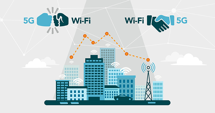
Which connectivity technology will win the battle—and is it a battle at all?
Some industry-watchers believe that this impressive growth has set 5G and Wi-Fi on a collision course. LitePoint holds a different view and believes that the two will operate symbiotically. Of course, historically, cellular and Wi-Fi have served different use cases. Users have typically preferred cellular for on-the-go, long-range communications with guaranteed latency and quality requirements. They’ve perceived Wi-Fi, on the other hand, as a short-range LAN technology offering better data rates. The common thinking pegged Wi-Fi as the better choice for households or sizeable premises as it offers the option to tailor the network for a certain user density and application.
Recently, however, 5G and Wi-Fi 6E/7 have emerged as feature-rich technologies with a healthy interdependency. With rising popularity in the residential broadband market, let’s explore how 5G and Wi-Fi 6E/7 are coming together as well as the prerequisites for successful adoption.
The Impact of 5G and Wi-Fi 6E/7 on Fixed Wireless Access
One prominent use case to emerge from the 5G/Wi-Fi shared environment is the growth of fixed-wireless access (FWA), which offers strong potential to benefit both private and enterprise networks.
For years, private networks relied on fixed broadband for internet connectivity, but this has come at a cost because these networks require heavy capital investment, time and effort. Conversely, FWA leverages traditional broadband with wireless connectivity far more efficiently and affordably because it uses customer premises equipment (CPE).
With FWA, the CPE acts as the router, but instead of connecting to the internet via wired broadband, it uses 5G to connect wirelessly to the internet. Then, the devices within the private network connect to the CPE via standard Wi-Fi. In this capacity, the concept of FWA is only made possible through the newfound synergy between 5G and Wi-Fi.
Benefits of FWA
From an operator’s perspective, there are a few pivotal advantages:
- Reusability of 5G spectrum and infrastructure: Allows operators to fully exploit existing 5G spectrum and mobile broadband assets to deploy FWA services. Operators can bring down the 5G cost-per-bit delivered to their customers and attain higher returns on infrastructure investment.
- Scalability: Gives carriers the ability to offer higher data rates and extend connectivity from single to multiple users without requiring infrastructure-level modification. Consumers also benefit: They simply need to access comprehensive, function-packed CPE equipment.
Although these advantages deliver new revenue opportunities for operators, they are contingent upon consumer adoption of the service, the cost of CPE devices and overall time-to-market.
From a consumer’s point of view, the two biggest factors driving FWA adoption are:
- Performance: In the case of private and enterprise networks, Quality of Service (QOS) plays a crucial role in driving the transition from fixed broadband to fixed wireless. In fact, many operators are now offering “speed tiers” in addition to volume-tariff plans to enable higher monetization and extend services to small/medium enterprises. Here’s where comprehensive testing becomes critical. Testing verifies antenna performance and ensures power calibration and coexistence assessments that have a direct impact on end-to-end throughput and end-user QoS.
- Cost: The lower upfront cost of CPE installation and monthly service fees will expedite pervasive adoption of FWA. The widespread commercial success of FWA, however, largely rests in the hands of the operators and OEMs given that the cost of development and manufacturing eventually gets passed down to the consumer.
Bringing Down Cost Through Robust Testing
In the case of FWA, operators typically sell white-label CPE products, which are designed and manufactured by a third party. Given their limited control over these products, operators can help to keep both cost and product quality in check through robust test and measurement. Investing in a high-performance RF test solution not only safeguards device quality and brand reputation, but also brings down after-sales expenses, including returns, replacements and service-center costs that result from shipping poor-quality products. These RF test solutions include:
- Multi-device testing: Parallel test capability in manufacturing is a multi-pronged approach that can improve throughput and minimize test costs while increasing production test efficiency.
- Turnkey automation test tool: Often, chipset-specific test tools come with the added expense of licensing fees and labor-intensive correlation and debugging. In contrast, an automated test tool that’s pre-validated on chipset-specific libraries can significantly reduce the time and effort of in-house test tool development.
Conclusion
As 5G and Wi-Fi 6E/7 evolve a complementary relationship, new technologies like FWA for private networks are now commercially viable. Ultimately, however, 5G FWA is only as good as the performance of the underlying CPE. Thus, it’s critical to thoroughly test the CPE for considerations such as antenna performance, power calibration, coexistence testing and end-to-end throughput before deployment.
LitePoint is accelerating the future of 5G FWA for enterprises by addressing these needs head-on through our advanced testing equipment for modern CPEs. Learn more about LitePoint solutions for 5G FWA and Wi-Fi 6E/7 through our webinars, videos, and website. Or email us today with your questions.