GREENSBORO, NC – November 28, 2022 – Qorvo® (Nasdaq: QRVO), a leading global provider of connectivity and power solutions, announced today that it has secured multiple design wins in collaboration with MediaTek that extend Qorvo’s leadership in 5G smartphones and include mobile Wi-Fi, Wi-Fi routers, and 5G/Wi-Fi automotive platforms.
Dave Fullwood, Qorvo senior vice president of Sales and Marketing, said, “Qorvo is pleased to expand our collaboration with MediaTek to enable the power of connectivity in a new generation of 5G smartphones, Wi-Fi equipment and cars. Qorvo works closely with MediaTek to accelerate innovation and deliver cutting-edge performance to leading customers in mobile, networking, automotive and other markets.”
The automotive design wins are with tier 1 suppliers and will enable 5G connectivity in 2023 automotive platforms. Qorvo’s 5G automotive solutions are optimized with MediaTek to support enhanced safety and entertainment features including telematics, advanced driver-assistance systems (ADAS), autonomous driving, emergency calling (eCall) and in-vehicle connectivity and entertainment services. Qorvo’s automotive connectivity portfolio enables complete AECQ-qualified connectivity solutions – from onboard telematics to the shark fin antenna.
Qorvo has also secured Wi-Fi 6, Wi-Fi 6E and Wi-Fi 7 design wins in a range of devices including service provider gateways and smartphones. Qorvo mates its advanced filters and Wi-Fi integrated front end modules (iFEMs) with MediaTek Wi-Fi systems-on-chip (SoCs) to deliver end-to-end Wi-Fi solutions that increase throughput, reduce latency and enhance the quality of client connections.
In smartphones, Qorvo has secured multiple design wins with leading OEMs that span Qorvo’s broad portfolio of highly integrated advanced cellular solutions. The global smartphone market is supported by multiyear content and integration trends, with outsized opportunities among MediaTek customers as Android OEMs migrate their portfolios to higher performing 5G devices.
Qorvo is a trusted supplier with Approved Vendor List (AVL) accreditation on multiple MediaTek cellular and Wi-Fi reference designs. The reference designs combine MediaTek chipsets and SoCs with Qorvo’s extensive portfolio of RF front end solutions to deliver superior throughput, latency, power efficiency and range. Qorvo’s advanced cellular and connectivity solutions support all major wireless protocols, including Matter®, Bluetooth® Low Energy (BLE), Zigbee, Thread, UWB, Wi-Fi 6/6E/7, CAT-M, NB-IoT and 5G.
About Qorvo
Qorvo (Nasdaq: QRVO) supplies innovative semiconductor solutions that make a better world possible. We combine product and technology leadership, systems-level expertise and global manufacturing scale to quickly solve our customers’ most complex technical challenges. Qorvo serves diverse high-growth segments of large global markets, including consumer electronics, smart home/IoT, automotive, EVs, battery-powered appliances, network infrastructure, healthcare and aerospace/defense. Visit www.qorvo.com to learn how our diverse and innovative team is helping connect, protect and power our planet.
Qorvo is a registered trademark of Qorvo, Inc. in the U.S. and in other countries. All other trademarks are the property of their respective owners.
This press release includes “forward-looking statements” within the meaning of the safe harbor provisions of the Private Securities Litigation Reform Act of 1995. These forward-looking statements include, but are not limited to, statements about our plans, objectives, representations and contentions, and are not historical facts and typically are identified by use of terms such as “may,” “will,” “should,” “could,” “expect,” “plan,” “anticipate,” “believe,” “estimate,” “predict,” “potential,” “continue” and similar words, although some forward-looking statements are expressed differently. You should be aware that the forward-looking statements included herein represent management’s current judgment and expectations, but our actual results, events and performance could differ materially from those expressed or implied by forward-looking statements. We do not intend to update any of these forward-looking statements or publicly announce the results of any revisions to these forward-looking statements, other than as is required under U.S. federal securities laws. Our business is subject to numerous risks and uncertainties, including those relating to fluctuations in our operating results; our substantial dependence on developing new products and achieving design wins; our dependence on several large customers for a substantial portion of our revenue; continued volatility and uncertainty in customer demand, worldwide economies and financial markets resulting from the impact of the COVID-19 pandemic, conflict in Ukraine or other macroeconomic factors; a loss of revenue if defense and aerospace contracts are canceled or delayed; our dependence on third parties; risks related to sales through distributors; risks associated with the operation of our manufacturing facilities; business disruptions; poor manufacturing yields; increased inventory risks and costs, including under long-term supply agreements, due to timing of customers’ forecasts; our inability to effectively manage or maintain evolving relationships with chipset suppliers; our ability to continue to innovate in a very competitive industry; underutilization of manufacturing facilities; unfavorable changes in interest rates, pricing of certain precious metals, utility rates and foreign currency exchange rates; our acquisitions and other strategic investments failing to achieve financial or strategic objectives; our ability to attract, retain and motivate key employees; warranty claims, product recalls and product liability; changes in our effective tax rate; changes in the favorable tax status of certain of our subsidiaries; enactment of international or domestic tax legislation, or changes in regulatory guidance; risks associated with environmental, health and safety regulations, and climate change; risks from international sales and operations; economic regulation in China; changes in government trade policies, including imposition of tariffs and export restrictions; we may not be able to generate sufficient cash to service all of our debt; restrictions imposed by the agreements governing our debt; our reliance on our intellectual property portfolio; claims of infringement of third-party intellectual property rights; security breaches and other similar disruptions compromising our information; theft, loss or misuse of personal data by or about our employees, customers or third parties; provisions in our governing documents and Delaware law may discourage takeovers and business combinations that our stockholders might consider to be in their best interests; and volatility in the price of our common stock. These and other risks and uncertainties, which are described in more detail under “Risk Factors” in Part I, Item 1A. of our Annual Report on Form 10-K for the year ended April 2, 2022 and Qorvo’s subsequent reports and statements filed with the Securities and Exchange Commission, could cause actual results and developments to be materially different from those expressed or implied by any of these forward-looking statements.
GREENSBORO, NC – September 13, 2022 – Qorvo® (Nasdaq: QRVO), a leading global provider of connectivity and power solutions, today unveiled a compact integrated front-end module (iFEM) that provides power-efficient and reliable whole-home coverage for Wi-Fi 6 (802.11ax) and eventually Wi-Fi 7 systems. The QPF7250 iFEM extends Wi-Fi range by 30% over competing devices while increasing capacity to support more access points for smart homes and the Internet of Things (IoT).
The Qorvo’s QPF7250 integrates a 2.4 GHz power amplifier (PA) with DC and RF power detectors, an FCC edgeBoost™ Bulk Acoustic Wave (BAW) filter, a transmit-receive switch (SP2T) and a bypassable low noise amplifier (LNA) into a single device. Qorvo edgeBoost filtering technology provides unique capability to maximize capacity and range by eliminating the need to reduce output power on any Wi-Fi channels to meet regulatory requirements. Its power amplifier has been optimized for efficiency resulting in 0.35 Watt lower power dissipation over previous generations.
Tony Testa, Qorvo director of Wireless Connectivity Product Marketing, said, “Qorvo’s newest iFEM provides superior power efficiency – up to 1.4 Watt savings in a 4-stream router – better than any other integrated FEM. The very compact QPF7250 makes possible smaller, less intrusive access points and wireless routers. This device is the latest in a growing Qorvo family of highly integrated products that will address operational and architectural flexibility for Wi-Fi 6 and 7 systems, and includes solutions for home gateways, routers and enterprise deployments.”
The QPF7250 iFEM uses 15% less power and generates less heat while increasing range by approximately 10% through higher regulatory-compliant power and leading throughput across Wi-Fi channels 1 through 11. It provides improved range, capacity and coexistence across all available channels, significantly increasing the quality of service. Qorvo iFEMs reduce time to market by resolving integration challenges within the module and delivering assured RF-tested performance. The reduced part count also lowers the bill of materials cost and overall cost of ownership.
QPF7250 samples and production devices are available from Qorvo and authorized distributors.
Qorvo’s Wireless Connectivity (WCON) business is a leading developer of wireless semiconductor system solutions for connected devices that support Wi-Fi, Zigbee, Thread and Bluetooth® Low Energy. WCON offers integrated Wi-Fi front ends and an extensive portfolio of advanced RF chips and software for the Internet of Things. More information about the company’s Wi-Fi innovation can be found at https://www.qorvo.com/innovation/wi-fi.
About Qorvo
Qorvo (Nasdaq: QRVO) supplies innovative semiconductor solutions that make a better world possible. We combine product and technology leadership, systems-level expertise and global manufacturing scale to quickly solve our customers’ most complex technical challenges. Qorvo serves diverse high-growth segments of large global markets, including consumer electronics, smart home/IoT, automotive, EVs, battery-powered appliances, network infrastructure, healthcare and aerospace/defense. Visit www.qorvo.com to learn how our diverse and innovative team is helping connect, protect and power our planet.
Qorvo is a registered trademark of Qorvo, Inc. in the U.S. and in other countries. All other trademarks are the property of their respective owners.
Media Contact:
Cindy Warschauer
Marketing Communications Manager
Qorvo Wireless Connectivity Products
W +1-972-994-8546
This press release includes “forward-looking statements” within the meaning of the safe harbor provisions of the Private Securities Litigation Reform Act of 1995. These forward-looking statements include, but are not limited to, statements about our plans, objectives, representations and contentions, and are not historical facts and typically are identified by use of terms such as “may,” “will,” “should,” “could,” “expect,” “plan,” “anticipate,” “believe,” “estimate,” “predict,” “potential,” “continue” and similar words, although some forward-looking statements are expressed differently. You should be aware that the forward-looking statements included herein represent management’s current judgment and expectations, but our actual results, events and performance could differ materially from those expressed or implied by forward-looking statements. We do not intend to update any of these forward-looking statements or publicly announce the results of any revisions to these forward-looking statements, other than as is required under U.S. federal securities laws. Our business is subject to numerous risks and uncertainties, including those relating to fluctuations in our operating results; our substantial dependence on developing new products and achieving design wins; our dependence on several large customers for a substantial portion of our revenue; the COVID-19 pandemic materially and adversely affecting our financial condition and results of operations; a loss of revenue if defense and aerospace contracts are canceled or delayed; our dependence on third parties; risks related to sales through distributors; risks associated with the operation of our manufacturing facilities; business disruptions; poor manufacturing yields; increased inventory risks and costs due to timing of customer forecasts; our inability to effectively manage or maintain evolving relationships with platform providers; our ability to continue to innovate in a very competitive industry; underutilization of manufacturing facilities as a result of industry overcapacity; unfavorable changes in interest rates, pricing of certain precious metals, utility rates and foreign currency exchange rates; our acquisitions and other strategic investments failing to achieve financial or strategic objectives; our ability to attract, retain and motivate key employees; warranty claims, product recalls and product liability; changes in our effective tax rate; changes in the favorable tax status of certain of our subsidiaries; enactment of international or domestic tax legislation, or changes in regulatory guidance; risks associated with environmental, health and safety regulations and climate change; risks from international sales and operations; economic regulation in China; changes in government trade policies, including imposition of tariffs and export restrictions; we may not be able to generate sufficient cash to service all of our debt; restrictions imposed by the agreements governing our debt; our reliance on our intellectual property portfolio; claims of infringement of third-party intellectual property rights; security breaches and other similar disruptions compromising our information; theft, loss or misuse of personal data by or about our employees, customers or third parties; provisions in our governing documents and Delaware law may discourage takeovers and business combinations that our stockholders might consider to be in their best interests; and volatility in the price of our common stock. These and other risks and uncertainties, which are described in more detail in Qorvo’s most recent Annual Report on Form 10-K and in other reports and statements filed with the Securities and Exchange Commission, could cause actual results and developments to be materially different from those expressed or implied by any of these forward-looking statements.
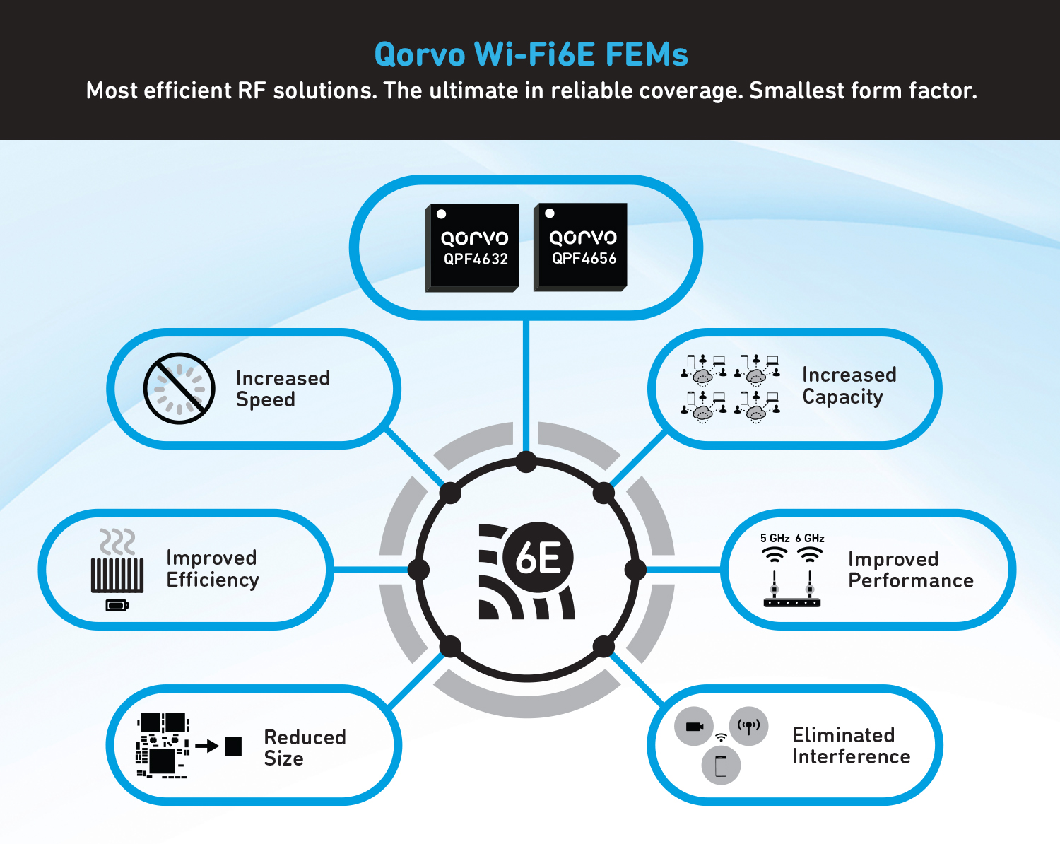
GREENSBORO, NC – January 12, 2021 – Qorvo® (Nasdaq:QRVO), a leading provider of innovative solutions that connect and power the world, today introduced two Wi-Fi 6E front end modules (FEMs) designed to maximize throughput and range in high-bandwidth applications such as 8K video streaming, online gaming and virtual reality.
Wi-Fi 6E is an extension of Wi-Fi 6 that operates in the recently opened 6 GHz frequency band, in addition to the traditional 2.4 GHz and 5 GHz bands. Wi-Fi 6E triples Wi-Fi capacity with contiguous spectrum to accommodate 7 additional 160 MHz-wide channels or 14 additional 80 MHz channels. Qorvo’s Wi-Fi 6E FEMs unleash the full potential of this new spectrum, delivering leading linearity performance and maximizing throughput and capacity at peak permissible indoor power levels.
The Qorvo QPF4656 and QPF4632 deliver robust and rugged performance with world-class energy efficiency, and the highest speed and throughput at the maximum power levels supported by Wi-Fi 6E’s extended bandwidth. The QPF4656 is designed for consumer Wi-Fi 6E routers and gateways. The QPF4632 is designed for enterprise power-over-ethernet (POE) Wi-Fi 6E products and applications.
The Qorvo Wi-Fi 6E FEMs deliver up to 25% more power efficiency than current solutions in compact packaging, enabling cost, size and thermal performance advantages in consumer and enterprise wireless networking solutions.
Cees Links, general manager of Qorvo’s Wireless Connectivity business, said, “Qorvo’s new Wi-Fi 6E FEMs deliver on the Wi-Fi 6E promise to enable high-bandwidth applications with faster data speeds and lower latency—and in smaller, more rugged form factors. Consumers and businesses will see significant improvements in home entertainment, gaming and social experiences.”
The QPF4656 and QPF4632 FEMs are sampling now.
Connect with us virtually during the all-digital CES® (#CES2021), January 11-14. For more information about Qorvo’s solutions, announcements and meeting inquiries, visit our Qorvo CES 2021 landing page.
Qorvo’s Wi-Fi portfolio serves a broad range of products from flagship smartphones and tablets, to consumer and enterprise gateway and smart home applications. Qorvo’s Wi-Fi 6 solutions enable significantly faster wireless upload and download speeds, increased capacity and improved power efficiency.
About Qorvo
Qorvo (Nasdaq: QRVO) makes a better world possible by providing innovative Radio Frequency (RF) solutions at the center of connectivity. We combine product and technology leadership, systems-level expertise and global manufacturing scale to quickly solve our customers’ most complex technical challenges. Qorvo serves diverse high-growth segments of large global markets, including advanced wireless devices, wired and wireless networks and defense radar and communications. We also leverage unique competitive strengths to advance 5G networks, cloud computing, the Internet of Things, and other emerging applications that expand the global framework interconnecting people, places and things. Visit www.qorvo.comto learn how Qorvo connects the world.
Qorvo is a registered trademark of Qorvo, Inc. in the U.S. and in other countries. All other trademarks are the property of their respective owners.
| Investor Relations Contact: Doug DeLieto VP, Investor Relations +1-336-678-7968 |
Media Contact: Katie Caballero Marketing Communications Manager Qorvo Infrastructure and Defense Products +1 972-994-8546 katie.caballero@qorvo.com |
This press release includes “forward-looking statements” within the meaning of the safe harbor provisions of the Private Securities Litigation Reform Act of 1995. These forward-looking statements include, but are not limited to, statements about our plans, objectives, representations and contentions, and are not historical facts and typically are identified by use of terms such as “may,” “will,” “should,” “could,” “expect,” “plan,” “anticipate,” “believe,” “estimate,” “predict,” “potential,” “continue” and similar words, although some forward-looking statements are expressed differently. You should be aware that the forward-looking statements included herein represent management’s current judgment and expectations, but our actual results, events and performance could differ materially from those expressed or implied by forward-looking statements. We do not intend to update any of these forward-looking statements or publicly announce the results of any revisions to these forward-looking statements, other than as is required under U.S. federal securities laws. Our business is subject to numerous risks and uncertainties, including those relating to fluctuations in our operating results; our substantial dependence on developing new products and achieving design wins; our dependence on a few large customers for a substantial portion of our revenue; a loss of revenue if contracts with the United States government or defense and aerospace contractors are canceled or delayed or if defense spending is reduced; the COVID-19 pandemic, which has and will likely continue to negatively impact the global economy and disrupt normal business activities, and which may have an adverse effect on our results of operations; our dependence on third parties; risks related to sales through distributors; risks associated with the operation of our manufacturing facilities; business disruptions; poor manufacturing yields; increased inventory risks and costs due to timing of customer forecasts; our inability to effectively manage or maintain evolving relationships with platform providers; risks from international sales and operations; economic regulation in China; changes in government trade policies, including imposition of tariffs and export restrictions; our ability to implement innovative technologies; underutilization of manufacturing facilities as a result of industry overcapacity; we may not be able to borrow funds under our credit facility or secure future financing; we may not be able to generate sufficient cash to service all of our debt; restrictions imposed by the agreements governing our debt; volatility in the price of our common stock; damage to our reputation or brand; fluctuations in the amount and frequency of our stock repurchases; our recent and future acquisitions and other strategic investments could fail to achieve financial or strategic objectives; our ability to attract, retain and motivate key employees; our reliance on our intellectual property portfolio; claims of infringement of third-party intellectual property rights; security breaches and other similar disruptions compromising our information; theft, loss or misuse of personal data by or about our employees, customers or third parties; warranty claims, product recalls and product liability; and risks associated with environmental, health and safety regulations and climate change. Many of the foregoing risks and uncertainties are, and will continue to be, exacerbated by the COVID-19 pandemic and any worsening of the global business and economic environment as a result. These and other risks and uncertainties, which are described in more detail in Qorvo’s most recent Annual Report on Form 10-K and in other reports and statements filed with the Securities and Exchange Commission, could cause actual results and developments to be materially different from those expressed or implied by any of these forward-looking statements.