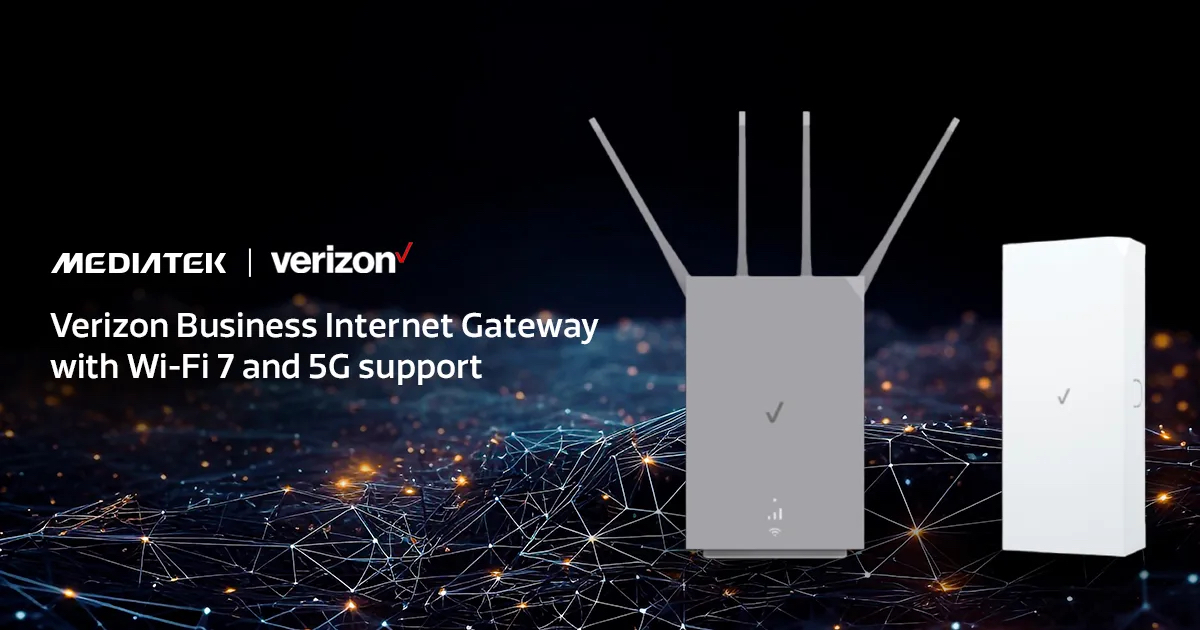
As one of the first adopters of Wi-Fi 7 technology, we wasted no time in establishing an ecosystem of fast, reliable and always-on products that enable MediaTek Filogic Wi-Fi 7 support. Recently, Verizon announced the launch of its network’s latest Business Internet Gateway, which marks the first product on Verizon’s network to use Wi-Fi 7, and is also one of the first devices in the world to support next-generation Wi-Fi connectivity features such as tri-band and 4×4 antenna capabilities.
The new Verizon Business Internet Gateway features MediaTek’s next-generation modem and router all in one device. In addition to Wi-Fi 7 support provided by the MediaTek Filogic 680, it utilizes the MediaTek T830 5G chipset, which comes with 4CC 300MHz 5G modem capability, 3GPP Release 16 functionality, and is capable of 5G speeds up to 7Gbps. The chip is made using a highly advanced 4nm process for significant power savings, and supports multiple Ethernet options, with speeds up to 10Gbps.
By working closely with Verizon to integrate MediaTek’s Wi-Fi 7 capabilities into the Gateway, users can now enjoy a router that comes with superior performance and design compared to competing FWA devices on the market. After years of development, we are looking forward to seeing the improved experiences that next-generation wireless technology enables for consumers and businesses in the United States.
The Verizon Business Internet Gateway is now available to its Business Internet customers. Learn more about MediaTek’s 5G Broadband and Wi-Fi 7 platforms >
– Provides new self-certification capability for broadband service providers, CPE manufacturers, and chipset suppliers to test integrations, ensure performance quality, and accelerate Smart Wi-Fi deployments
– Includes on-premises hardware and software used within test centers to increase efficiency and continuously validate data integrity across ecosystem of broadband CPE software
– Integral part of Airties’ portfolio of Wi-Fi software testing services
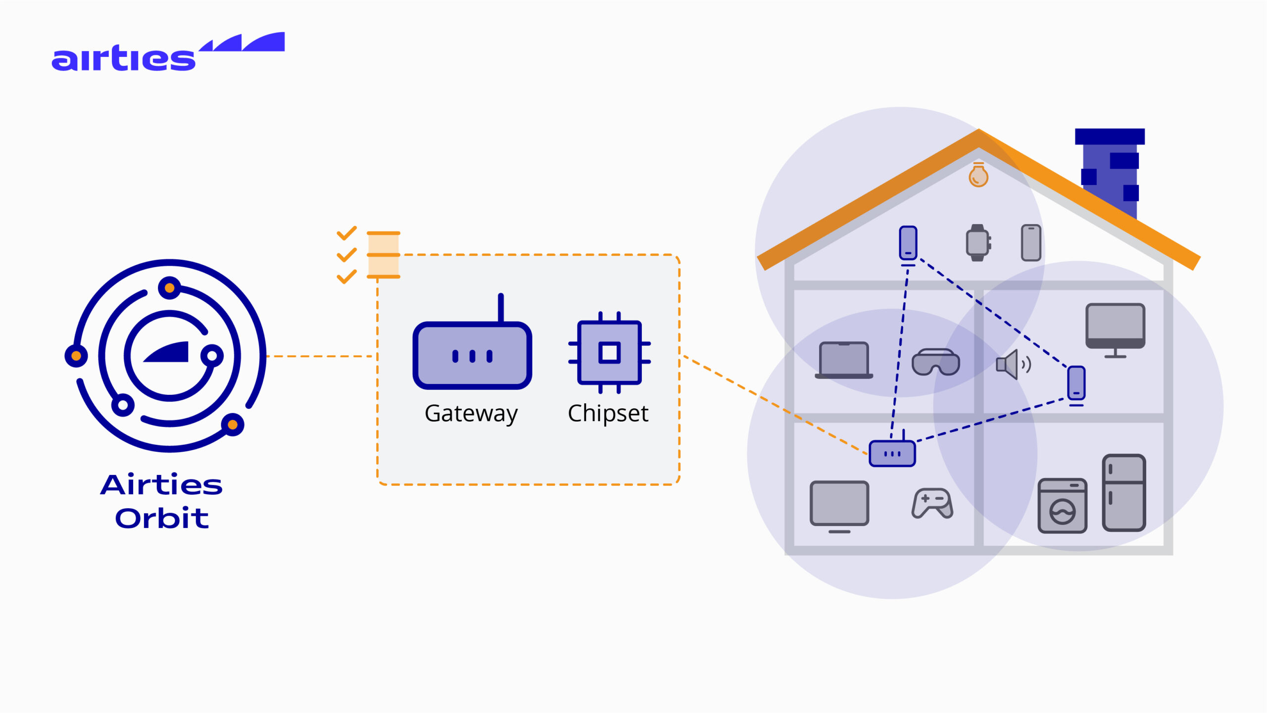
Paris, France – March 28, 2024 – Airties, a global leader of managed Wi-Fi solutions for broadband service providers, today announced the commercial launch of Orbit, a continuous test automation platform for broadband service providers, customer premises equipment (CPE) manufacturers, and system-on-chip (SoC) manufacturers to support Smart Wi-Fi integrations and deployments.
Airties Orbit addresses a longstanding industry pain point: ensuring consistent data accuracy and performance measurement criteria across diverse combinations of Wi-Fi chipsets, embedded software, and hardware (i.e. gateways/routers/extenders). With Orbit, broadband operators, and their suppliers, can continuously validate data tested during software changes and firmware updates; addresses common Wi-Fi performance issues; and accelerate time-to-market for managed Wi-Fi deployments through self-certification.
Traditionally, integrated testing of Wi-Fi software has been a manual, time-consuming process challenged by inconsistencies in test procedures, device and software functionality, and dissimilar test environments. These variabilities often lead to inaccuracies or misinterpretations. Resolving these issues involves complex multi-party troubleshooting efforts which can lead to product launch delays and added deployment costs. Airties Orbit addresses these challenges by providing a complete and automated testing platform installed on-premises at testing facilities of broadband service providers, CPE manufactures and SoC providers.
“Service providers need an efficient way to manage the variability of broadband software to ensure consistent quality home Wi-Fi, test the impact of software updates, and launch new products,” said Metin Taskin, Founder and Co-CEO of Airties. “Airties Orbit removes the complexity and inconsistencies of traditional testing methods, allowing operators, OEMs and SoC manufacturers to verify performance with confidence and speed. Orbit ensures the accuracy and completeness of data across tests, streamlines device onboarding, and improves efficiency through automation. This translates to faster time-to-market, reduced costs, and ultimately, a better Wi-Fi experience for everyone involved.”
With the launch of Orbit, Airties continues its commitment to solve critical challenges facing the ecosystem of broadband customers, partners, and suppliers. Airties Orbit is currently being deployed by leading broadband service providers, CPE manufacturers, and chipset suppliers around the globe.
Key benefits of Airties Orbit include:
Airties Orbit is now an integral part of Airties’ Wi-Fi software testing services for broadband service providers (see video here). Airties also provides access to multi-floor test homes that include custom robots, called AirBots, which run throughout homes to test devices and application performance in real-world environments. Customers can run hundreds of fully automated Wi-Fi tests including basic system testing, performance testing, functional tests, and interoperability tests. Tests can be tailored to specific needs or follow generic plans to test for throughput, stability, new OS performance, and more. Airties Wi-Fi software testing helps address ecosystem complexity, anticipate future demands, and delivers fast and cost-effective Wi-Fi software validation.
Airties has been recognized with many prestigious industry awards for its innovative work serving broadband operators, including: “Best Home Wi-Fi Solution Award” from Broadband World Forum; “Best Wi-Fi Service Provider Solution” and “Best Home Wi-Fi Product” awards from Wi-Fi NOW; “Best Wi-Fi Innovation” and “Best-In Home Wi-Fi Network” awards fromWireless Broadband Alliance; “Best Broadband Customer Experience” from Cable & Satellite International; and many others. Additional information about Airties can be found at:www.airties.com.
About Airties
Airties is a leading provider of managed Wi-Fi solutions to operators around the globe. The Smart Wi-Fi portfolio from Airties includes Airties Edge, smart Wi-Fi software for gateways; Airties Cloud management platform and its companion app; and Wi-Fi mesh extenders. Operators turn to Airties for the design, implementation, and ongoing optimization of their customers’ broadband experience. Airties’ customers include AT&T, Deutsche Telekom, Singtel, Sky, Telia, Telstra, Vodafone, and many others. More information is available at www.airties.com.
###

Wi-Fi HaLow is an exciting technology to address application use-cases such as security cameras, industrial monitoring, and a wide range of other indoor and outdoor IoT deployments. Our video series, 3 for 3, provides 3 answers for 3 pressing questions about trends in wireless test. In this video, Adam Smith discusses what is unique about Wi-Fi HaLow, where it is useful to deploy, and wireless test considerations for Wi-Fi HaLow devices.
Askey and Newracom Continue to Drive Wi-Fi HaLow Forward with the Development of Askey’s WAH0070 Wi-Fi HaLow Module Based on Newracom NRC7394 SoC
IRVINE, Calif., March 20, 2024 (Newswire.com) – The advancement of Wi-Fi HaLow persists, and adoption continues to grow, leading to the development of the next-generation Wi-Fi HaLow Module by Askey, utilizing the Newracom’s SOC (System on Chip), NRC7394. Wi-Fi HaLow, known for its long-range and low-power capabilities, has been gaining increased adoption. Askey’s decision to adopt Newracom’s Wi-Fi HaLow SoC is a resounding endorsement of the continued belief in the success of the new IoT-enabling Wi-Fi standard, IEEE 802.11ah.
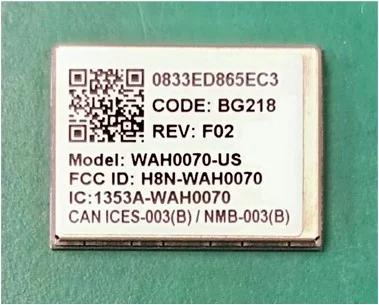
The WAH0070 Wi-Fi HaLow module by Askey features a compact footprint of 18mm by 13.5mm with a height of 2.1mm. It has been developed with an optional power amplifier, offering users the flexibility to maximize both distance and signal strength or opt for operation without the power amplifier to conserve battery life in low-power applications. This makes the module ideal for IoT applications, such as smart city infrastructure, building and factory automation, smart retail, security and surveillance systems, telematics, and long-range portable devices.
“We are pleased to collaborate with Newracom to develop a Wi-Fi HaLow module that can meet the needs of the next generation of IoT and Smart devices. Wi-Fi HaLow adoption has been steadily growing, and we’re honored to continue to be a leader in the Wi-Fi HaLow space,” stated Tommy Lin, 11ah Product Development AVP of Askey.
“We’re delighted to have a partner like Askey, who has aligned with our vision for the adoption of Wi-Fi HaLow as an innovative IoT connectivity bearer. ASKEY is at the forefront of providing smart applications, and their continued support of the Wi-Fi HaLow propels the true potential of the technology,” remarked Frank Lin, Vice President of Sales and Marketing at Newracom.
The WAH0070 Wi-Fi HaLow module by Askey marks another significant step forward in the Wi-Fi HaLow market. With its over-a-kilometer range, low power consumption, strong signal penetration, robust WPA3 security, and IP-based communication, Wi-Fi HaLow can accelerate the rapid development of smarter and more advanced IoT-based services. For more information, visit www.askey.com or https://newracom.com/products/nrc7394.
About Newracom, Inc.
Newracom, Inc., located in Irvine, California, U.S., has rapidly become a leading developer and supplier of IoT-enabled wireless connectivity chipsets. We specialize in providing a broad range of Wi-Fi (IEEE 802.11ah and IEEE 802.11b/g/n/ac/ax) that covers various connectivity needs in our lives. With our extensive and diverse Wi-Fi solutions, NEWRACOM enables customers with a “one-stop shop,” offering a comprehensive solution that can serve multiple IoT applications, including Smart Grid, Wearables, Smart Home and Office, Healthcare, and Industrial Automation. For more information, please visit online at https://www.newracom.com.
About Askey
Founded in 1989, Askey Computer Corp. specializes in creating solutions and ecosystems for those who want the best in Smart Connected environments.
Askey has been the preferred carrier-grade solution partner for communications providers, major Telecom Operators and Consumer Product Providers worldwide. To learn more, please visit: https://www.askey.com.
The Ads4WiFi Media Network is an easy way for venues to monetize their Wi-Fi network while also offering DOOH Advertising agencies access to an engaged audience
ST. PETERSBURG, FL, USA, March 20, 2024 /EINPresswire.com/ — In a world where connectivity is paramount and advertising opportunities are constantly sought after, the Ads4WiFi Media Network emerges as a groundbreaking solution, poised to revolutionize both public Wi-Fi access and digital out-of-home (DOOH) advertising. With its unique approach, Ads4WiFi addresses the longstanding issue faced by venues and public networks lacking the budgets to maintain or upgrade their Wi-Fi infrastructure.
The Ads4WiFi Media Network serves as both a broker and a platform, bridging the gap between venues seeking to monetize their Wi-Fi networks and DOOH advertising agencies hungry for impactful advertising spaces. Just as the real estate Multiple Listing Service (MLS) simplifies property transactions, Ads4WiFi streamlines the process for advertising agencies, offering them access to a master list of available public Wi-Fi venues. In addition, venues receive assistance on-boarding and managing campaigns no matter the hardware or captive portal platform they’re using.
“Today, connectivity is not just a luxury; it’s a necessity. However, many venues and municipal networks struggle to keep up with the costs of maintaining or upgrading their Wi-Fi infrastructure,” said Todd Myers, CEO of GoZone WiFi, who owns and operates the Ads4WiFi Media Network. “Ads4WiFi not only addresses this challenge but also unlocks a powerful avenue for DOOH advertising agencies to reach their target audiences in an innovative and impactful manner.”
The benefits of the Ads4WiFi Media Network extend beyond mere connectivity. By leveraging existing Wi-Fi infrastructure for advertising purposes, venues around the world can generate additional revenue streams while providing value-added services to their patrons. Meanwhile, advertisers gain access to prime advertising spaces in high-traffic areas, enhancing brand visibility and engagement.
Key features of Ads4WiFi Media Network include:
1. Centralized Platform: A user-friendly platform that consolidates available public Wi-Fi venues, making it easy for advertising agencies to browse, select and even request suitable locations for their campaigns.
2. Monetization Opportunities: Empowering venues to monetize their Wi-Fi networks by partnering with advertisers, creating a win-win scenario for both parties.
3. Targeted Advertising: Leveraging location-based targeting capabilities to deliver tailored advertising content to audiences based on their physical proximity to Wi-Fi hotspots.
4. Performance Analytics: Providing detailed analytics and insights to advertisers, allowing them to measure the effectiveness of their campaigns and optimize their strategies accordingly.
5. Technical and Campaign Support: The Ads4WiFi Media Network team assists both the advertisers and the venues to make sure campaign delivery expectations are met.
With the Ads4WiFi Media Network, the era of struggling Wi-Fi networks and underutilized advertising spaces is coming to an end. By connecting venues with advertisers in a seamless and efficient manner, Ads4WiFi unlocks new possibilities for revenue generation and brand exposure in the digital age.
For more information about Ads4WiFi Media Network and its innovative solutions, please visit https://www.ads4wifi.com.
About the Ads4WiFi Media Network:
The Ads4WiFi Media Network, owned and operated by GoZone WiFi which specializes in software platforms that monetize Wi-Fi networks, is a pioneering service that revolutionizes public Wi-Fi access monetization and out-of-home advertising. By serving as a broker and platform, Ads4WiFi connects venues seeking to monetize their Wi-Fi networks with DOOH advertising agencies, facilitating mutually beneficial partnerships. With its user-friendly interface, advanced features, and support, Ads4WiFi empowers venues to generate additional revenue streams while providing advertisers with prime advertising engagements in high-traffic areas.
Austin, TX and Washington, DC – March 12, 2024 – Wi-Fi Alliance® congratulates the NTIA spectrum team on the release of the National Spectrum Strategy Implementation Plan. This plan is an essential roadmap for collaboration between Federal and non-Federal stakeholders in the effort to address Americans’ ever-increasing need for wireless connectivity. We look forward to contributing to its implementation.

When you switch on a brand-new cellular or wired IoT device, it can be bootstrapped to connect to a provisioning server immediately. The IoT connectivity is secure and seamless from the moment the device is switched on.
This is not the case with Wi-Fi-based IoT devices. We have all tried to onboard these devices to the Wi-Fi network using an app, QR code, or Bluetooth, which may be okay for consumer devices. But what about industrial and enterprise use cases with thousands of devices? The onboarding issue is currently the largest showstopper for a mass market of Wi-Fi-based IoT devices.
At Enea, we have tried to solve this with the Zero-touch Wi-Fi IoT onboarding invention utilizing the already installed device certificates. The idea is excellent, but it requires industrywide acceptance and deployment. This was before OpenRoaming.
We now see the potential in using OpenRoaming to make Wi-Fi IoT onboarding as secure and seamless as Cellular and Wired IoT. It is a complex task with many use cases, and it may require a separate base RCOI for IoT and a different set of CAG policies. But it can be done.
The FIDO Alliance is leading the way in automatically onboarding IoT and headless devices. They have a well-thought-out process with their FIDO Device Onboard (FDO), an automatic onboarding protocol for edge nodes and IoT devices. FDO enables late binding of device credentials so that one manufactured device may be onboarded to many different cloud and edge management platforms. But to perform this late binding of credentials, the device needs connectivity to reach a so-called Rendezvous Service. This works well for wired and cellular devices that get connected when powered up but not for Wi-Fi-based IoT devices.
We are happy to announce that Enea and Intel have taken the initiative to form a working group within WBA called OpenRoaming & FIDO Device Onboarding with the mission to use OpenRoaming for a zero-touch connectivity for Wi-Fi-based IoT devices. The work is still in its initial stage, the goal is to make FDO as seamless for Wi-Fi as it is for fixed and cellular.
Eco-Friendly Speed Testing to Ensure New LiveBox 7 Performance |
|
|
PARIS, France – 21 February 2024 – In an innovative move in 2023, Orange France launched the LiveBox 7, its latest home gateway with enhanced performance and eco-friendly features capable of delivering ultra-fast internet speeds up to eight Gbps for businesses. Leveraging Wi-Fi 6E and SoftAtHome’s Wifi’ON, the LiveBox 7 supports multiple devices across its three frequency bands. To validate these high-speed claims, SoftAtHome has engineered an eco-conscious speed test. |
|
|
This new speed test serves at least four crucial functions: |
|
|
|
|
SoftAtHome’s speed test technology is designed with the environment in mind, minimizing the network’s energy use while ensuring swift and accurate performance assessments in less than a second. This solution is already in use by various operators across Europe, Asia, and the Americas, demonstrating its global applicability and effectiveness. |
|
|
Ollivier Courtel, Marketing Director, Connected Devices and Connectivity at Orange France, stated, “SoftAtHome stands as Orange’s preferred partner in fulfilling the commitments made to its valued connected home customers.” |
|
|
“We are thrilled to partner with Orange France to deploy our carrier-grade speed test solution” said David Viret-Lange, CEO of SoftAtHome. “This collaboration is a testament to our commitment to superior service experiences and operational efficiency. Our innovative tool ensures that Orange France can deliver the highest quality of service that their customers expect and deserve in 2024.” |
|
|
|
|
|
About SoftAtHome SoftAtHome is a leading software provider in six domains: broadband (Connect’ON), Wi-Fi (Wifi’ON), Security (Secure’ON), Smart Home (Things’ON), video (Watch’ON), and analytics/QoE monitoring (Eyes’ON). Their prowess is evident in over 30 million home networks and countless mobile devices worldwide, supported by Telecom and Broadcast operators. A majority operator-owned enterprise with a dedicated 300-member team, SoftAtHome actively participates in open-source communities such as prpl and RDK. Their innovative hybrid solutions adeptly combine top-tier Cloud-based software with software embedded in diverse mobile and fixed devices. For further information, visit: www.softathome.com or contact: contact@softathome.com. |
|
|
For Press Information Contact: Marta Twardowska-Rienks for SoftAtHome M: +31 621-184-585 X: @SoftAtHome |
Single instrument combines edge network vulnerability scanning with Wi-Fi and BT/BLE
wireless network performance testing and surveying.
Colorado Springs, Colorado, USA – March 5, 2024 – Today, NetAlly announced the expansion of
its cybersecurity assessment product line with the addition of CyberScope® Air, a Wi-Fi
vulnerability scanner and tester for assessing the security posture of WLANs against policies,
generating compliance reports, and performing ongoing monitoring for changes.
“The CyberScope family of tools are the first and only devices I’ve seen that can address
network security in meaningful ways at the network edge,” says Jennifer Minella, cybersecurity
author and co-host of the Packet Protector podcast.
Minella continues, “These tools bridge the gap between security and network operations in
meaningful ways, by allowing on-demand or pre-configured security assessments to test for the
vulnerabilities and misconfigurations that most often contribute to breaches, malware, and
other incidents.”
In April last year, NetAlly introduced CyberScope, the world’s first wired Ethernet and wireless
handheld edge network vulnerability scanner for in-depth cybersecurity assessments.
CyberScope Air offers a wireless-only version for security practitioners and network engineers
focused on wireless edge networks.
“With the massive proliferation of endpoints and ubiquitous connectivity in edge networks,
security professionals need a fast and easy way to have ‘eyes on’ all of the devices at the sites
they manage,” says James Kahkoska, NetAlly CTO.
With today’s announcement, NetAlly amplifies the power of CyberScope’s discovery capabilities
with new capabilities in their Link-Live collaboration, reporting and analytics platform, providing
fast insight into the devices in a site network over time.
New graphical dashboards provide instant insight into endpoints and network configurations
allowing easy exploration in chart, table, or topology views. The Discovery Monitoring feature
allows automated daily, weekly, or monthly snapshots to be uploaded to Link-Live to track new
and missing devices or Wi-Fi access points and clients. Powerful filtering and grouping allow
NetAlly, LLC ● 2075 Research Pkwy – Suite 190 ● Colorado Springs, CO 80920 simplicity ● visibility ● collaboration
analysis to instantly identify new devices, changes within a device, or for tracking specific
devices and types over time.
Mike Parrottino, NetAlly CEO adds, “The release of CyberScope Air is another milestone in
NetAlly’s efforts to bring our thirty years of experience in network visibility technology to
cybersecurity professionals whose current toolset lacks in-depth, tactical situational awareness
in edge networks.”
According to NetAlly, their CyberScope family of products help security practitioners by:
Easily validating security controls at the edge.
Inventorying everything including IoT, OT, unmanaged devices.
Quickly testing and demonstrating policy compliance.
Enabling collaboration and sharing between teams.
For more information, visit https://cyberscope.netally.com
About NetAlly
For decades, the NetAlly ® family of network test and analysis solutions has been helping
network and cybersecurity professionals better deploy, manage, maintain, and secure today’s
complex wired and wireless networks. Since creating the industry’s first handheld network
analyzer in 1993, NetAlly continues to set the standard for portable network analysis and
cybersecurity assessment with tools that include EtherScope® nXG, CyberScope®, AirMagnet®,
LinkRunner ® , LinkSprinter®, AirCheck™, and more. NetAlly simplifies the complexities of
network testing and cybersecurity assessments, provides instant visibility for efficient problem
resolution, and enables seamless collaboration between site personnel and remote experts. To
learn more and see how NetAlly helps network and security professionals get their jobs done
faster, visit https://netally.com, follow us on Facebook, Twitter, Linked-in, Instagram or
YouTube
Bangalore, February 26, 2024 — Aprecomm, a prominent network intelligence company , has announced a strategic alliance with Actiontec, one of the leading suppliers of connectivity devices. This collaboration aims to incorporate Aprecomm’s Network Intelligence products into Actiontec’s portfolio of OpenWiFi access points.. Aprecomm Virtual Wireless Expert (VWE) is a cutting-edge AIOps solution that harnesses the power of big data and machine learning. It offers Wi-Fi intelligence, streamlines IT operations, boosts efficiency, and simplifies network management.
Aprecomm’s network intelligence solution will be accessible on all Actiontec WiFi 6 access points running OpenWiFi, an open and disaggregated technology from developed by the Telecom Infra Project. Aprecomm’s technology will enhance performance overall performance of managed service providers’ Wi-Fi network operations. Users from various sectors such as enterprises, schools, hospitals, and MDUs, hospitality, among others, with ongoing network expansion requirements can now take advantage of the new self-organizing capabilities on Actiontec’s OpenWiFi-capable access points which include Intelligence Frequency Selection (IFS), Intelligence Client Steering (ICS), Intelligence Cell Adapt (ICA).
Aprecomm is achieving End-End QoE Assurance with Network Automation with products like Virtual Wireless Expert. We are happy to bring VWE to all Actiontec OpenWiFi products with this collaboration. By optimizing the network experience, VWE will provide a quick ROI to service providers,” said Pramod Gummaraj, CEO of Aprecomm.
Customers using Actiontec OpenWiFi-capable access points can effortlessly enable the service by subscribing as needed and smoothly incorporate the Intelligent service into their current Wi-Fi networks. Aprecomm and Actiontec are transforming Wi-Fi connectivity by greatly reducing downtimes and improving the overall network experience. Thanks to AI algorithms and VWE’s cutting-edge technology, IT teams can now effortlessly detect and fix network problems across different networks, sites, access points, and end devices.
“Aprecomm VWE goes beyond traditional performance monitoring to quickly locate, diagnose, and respond to problems across different networks, sites, and devices with the power of AI” said Frank Lai, VP Business Development and Head of OpenWiFi Division, Actiontec “It allows IT teams to focus on driving business value as opposed to dealing with mundane tasks and enhances our OpenWiFi product offering,” Lai added.
Launched in 2021, OpenWiFi is a community-developed open-source platform designed to lower the cost of developing and operating Wi-Fi networks. OpenWiFi include a cloud controller SDK and switches and enterprise-grade access point firmware validated to work seamlessly together. The platform’s unique approach to Wi-Fi creates an open-source disaggregated technology stack. The OpenWiFi technology was created by Telecom Infra Project (TIP), a global community of companies and organizations that are driving open and disaggregated infrastructure solutions to advance global connectivity.
About Aprecomm
Aprecomm is an industry game-changer with an Artificial Intelligence (AI) – enabled Software Stack to understand Customer Wi-Fi Experience. Aprecomm offers cloud-based automated solutions to enhance Wi-Fi performance. Aprecomm patented technology helps in automatically and proactively troubleshooting Wi-Fi issues. This way ISPs and Enterprises will be able to fix them immediately and dramatically minimize down-time. Aprecomm solutions help enterprises, Internet Service Providers (ISP) and Technology Service Providers (TSP) improve their business standards through higher reliability, reduced expenses, and speedy ROI.
About Actiontec
Take the in-home Internet and WiFi experience to the next level with Actiontec Electronics. Our groundbreaking Optim Managed Service Assurance Platform provides a flexible, scalable, and cloud-based platform that enables service providers to remotely manage, diagnose, optimize and secure home networks. With Optim, families can enjoy fast, reliable and safe Internet throughout the connected home, while providers can increase revenue and improve customer loyalty. Our award-winning products — including Gigabit Ethernet fiber routers, high-speed VDSL gateways and home networking solutions — are deployed by some of the largest telecom carriers in North America. As a minority owned company, we’re committed to promoting diversity and are actively pushing a variety of green programs designed to reduce the carbon footprint of our company and customers. Founded in 1993, Actiontec is headquartered in Santa Clara, CA, and maintains branch offices in Colorado Springs, CO; Shanghai, China; and Taipei, Taiwan.