




Breaking News

GLOBAL Wi-Fi NEWS bulletin

Imagine needing to connect a new building, parking lot, or sports field to your network. The vision is clear—but the reality of running fiber? That’s a whole different story. For IT leaders, the cost and complexity of digging, trenching, and laying cables can put projects on indefinite hold – imagine this challenge for cities and school districts working to close the digital divide in underserved and rural communities.

While fiber-optic cable is often considered the gold standard for connectivity, there are a few important factors to consider:

  • Time: Projects can be delayed and stretch on for months, as they often require trenching, environmental clearances, and can cause disruption to people in the surrounding area.
  • Obstacles: Highways, rivers, graveyards, and historic sites can make traditional cabling nearly impossible.
  • Cost: Expenses can range from $1 to $6 per foot. Urban projects may reach $40,000–$80,000 per mile, while rural deployments often higher due to difficult terrain and lengthy permitting.

Wireless backhaul provides a compelling alternative to physical cabling, using high-capacity wireless links to connect access points and extend network reach where fiber or copper would be too costly or time-consuming. Unlike traditional wired infrastructure, wireless backhaul can be deployed rapidly with minimal disruption, making it ideal for expanding connectivity to parking lots, adjacent building areas, or even entire communities and rural regions.

By addressing common cabling challenges—such as high costs, lengthy installation times, and geographic obstacles—wireless backhaul enables agile, scalable network expansion for everything from smart cities and industrial automation to community internet access. The result is connectivity that is faster, more affordable, and far more inclusive.

Cisco’s access points make it easy for you to use URWB as a backhaul technology to extend your network and Wi-Fi for end-user access simultaneously. This means when you need to extend Wi-Fi to a new location, a single remote access point is all you need—simplifying installation, reducing hardware costs, and accelerating deployment.

Did you know? Cisco’s access points can simultaneously extend your network with URWB and deliver Wi-Fi access simultaneously—so extending your network is now even easier.

Let’s explore three practical use cases URWB helps you connect farther, faster, and smarter.

  1. Bring Wi-Fi Where You Never Thought Possible. Whether you’re overseeing a university campus, healthcare complex, or corporate HQ, your network often needs to reach places fiber just can’t go—at least not easily or affordably. Think parking lots, outdoor event spaces, or new temporary structures. With Cisco access points, you can quickly bridge these gaps— extending your network with URWB and enabling seamless Wi-Fi for students, employees, or guests wherever they need it. Deployment is fast and flexible, with access points installed on rooftops, light poles, or existing infrastructure—no digging required.
  1. Extend Physical Security Beyond the Building. Modern security requires eyes everywhere. But placing cameras at the perimeter of a facility, near parking areas, or covering outdoor assets can be cost-prohibitive if you rely on trenching cable. With URWB, you can connect cameras and sensors across your property—delivering the bandwidth and reliability you’d expect from fiber, without the cost or delay. This is ideal for campus perimeters, athletic fields, or remote storage areas within your grounds.
  1. Quickly Connect Communities, New or Temporary Buildings. Need to bring connectivity to a modular classroom, event tent, or a newly built annex? Or maybe extend connectivity to under connected neighborhoods? Running fiber might not be practical—or possible on short notice. URWB lets you set up high-performance links in days, not weeks, helping you adapt to changing needs. Cisco URWB empowers communities to bridge these gaps—connecting city buildings, libraries, or distant school campuses with robust, scalable wireless links, Wi-Fi can be enabled in the access point to provide access to end-user devices. This flexibility makes it ideal for temporary classrooms, construction trailers, or pop-up health clinics on your property.

Real-world solutions

Organizations are putting these ideas to work—right now:

Canutillo Independent School District, Texas

“We needed to extend reliable connectivity to our athletic fields and remote campus buildings, and traditional fiber just wasn’t feasible. With Cisco’s wireless backhaul, we connected every corner of our district—quickly and cost-effectively.”
— Gary Gomez, Executive Director of Technology, Canutillo ISD

City of Fort Worth

“We saved substantial time and money by deploying Cisco’s wireless backhaul instead of running new fiber. The reliability and performance exceeded our expectations, even in challenging urban environments.”
— Kevin Gunn, Chief Technology Officer, City of Fort Worth

Break Connectivity Barriers—No Cables Required

Cisco’s URWB isn’t about replacing every fiber run—it’s about giving IT leaders the flexibility to extend networks where it matters most, when it matters most. With enterprise-grade reliability, simple deployment, and the ability to scale as your needs grow, Cisco URWB helps you rapidly extend your network wherever you need.

Cisco access points supporting both Wi-Fi and URWB simultaneously offer:

  • Rapid deployment: No cabling, no delays—just a clear path and power at each access point
  • Rock-solid reliability: Backhaul technology engineered for mission-critical applications.
  • Flexible coverage: Extend your network exactly where you need it within your property.
  • Cost savings and simplified operations: One access point delivers both wireless backhaul and Wi-Fi, streamlining deployment and management.

If you’re ready to expand your network faster, more affordably, and with greater flexibility—learn more about Cisco URWB.

Automated Guided Vehicles (AGVs) and Autonomous Mobile Robots (AMRs) are transforming how goods move through modern warehouses, factories, and distribution centers. They’re faster, smarter, and more efficient than ever but only when they have the wireless connectivity they need to function without interruption.

At 7SIGNAL, we help organizations ensure that their AGVs and AMRs stay connected, operational, and efficient because a robot without Wi-Fi is just expensive cargo.

What Are AGVs and AMRs?

AGVs: Automated Guided Vehicles

AGVs are mobile robots that follow fixed routes or markers such as magnetic tape, QR codes, or wires to transport materials. They’re widely used in logistics and manufacturing for tasks like:

  • Pallet transport
  • Towing trailers
  • Assembly line delivery

They rely on centralized control systems and require consistent Wi-Fi to receive instructions and report status.

AMRs: Autonomous Mobile Robots

AMRs take things further. They use onboard sensors, LiDAR, SLAM (simultaneous localization and mapping), and AI to dynamically navigate their environment. Unlike AGVs, they don’t need fixed paths they adapt in real-time.

They require constant access to cloud-based maps, navigation intelligence, and fleet orchestration platforms, all of which depend on strong, stable wireless networks.

Why Connectivity Is Critical

Whether it’s an AGV awaiting new routing commands or an AMR recalculating a path around an obstacle, any Wi-Fi degradation means downtime, delays, or damage. Common problems include:

  • Roaming failure: Robots drop off the network when moving between APs
  • High latency: Impacts command-and-control responsiveness
  • Packet loss: Affects telemetry and location accuracy
  • Coverage gaps: Cause navigation blind spots or system halts

How We Help: 7SIGNAL and Digital Experience Monitoring

7SIGNAL & EYERIS AI provides independent, infrastructure-agnostic monitoring that helps you maintain a high-performance wireless environment for AGVs and AMRs. Here’s how:

1. Continuous Monitoring from the Client Perspective

Our mobile Wi-Fi sensors monitor:

  • Signal strength (RSSI)
  • Packet loss
  • Roaming performance
  • Channel interference
  • And over 600 more KPIs

This allows you to catch connectivity issues before your robots do.

2. Proactive Alerting & Troubleshooting

When roaming failures or latency spikes occur, 7SIGNAL provides:

  • Real-time alerts
  • Historical correlation with robot telemetry
  • Location-specific performance visibility

So your ops teams can fix the issue before it stops the floor.

3. Data-Driven Optimization

We help you fine-tune:

  • AP placement and handoff thresholds
  • Channel and band utilization
  • QoS policies for mission-critical devices

All based on actual robot connectivity performance, not guesswork.

Smart Robots Deserve Smart Wi-Fi

Your AGVs and AMRs are only as smart as the network they depend on. At 7SIGNAL, we make sure that wireless isn’t the weak link in your automation strategy. With full visibility and actionable insights, we help you:

  • Reduce AGV and AMR downtime
  • Avoid productivity losses
  • Scale your fleet with confidence

Want to learn how 7SIGNAL can optimize your warehouse for mobile automation?
Let’s talk. We’ll show you how to support your fleet—and the future of work.

Wi-Fi Offloading and the Device

The device is King

Let’s face it. The network selection, which cellular or Wi-Fi network to connect to, is entirely in the hands of the device and, ultimately, the user.

Apple is clear about this:

“When auto-joining networks, macOS, iOS, and iPadOS start with the most preferred network, followed by private networks, then public networks.”

The Apple device tries to connect to networks in this order:

  1. The user’s “most preferred” network
    Known networks are scored based on the user’s actions. If the user manually switches to a network, its score increases. If the user manually disconnects from a network, its score decreases. The “most preferred” network is the one with the highest score.
  2. A private network
    Private networks are those set up in homes and offices and can include the Personal Hotspot on the user’s iOS or iPadOS device. Devices with macOS, iOS, or iPadOS reconnect to known private networks in order of most recently joined.
  3. A public network
    Public networks are designed for general access in public places like hotels, airports, and coffee shops. Other examples include Passpoint (Hotspot 2.0) and EAP-SIM/AKA/AKA′ in Wi-Fi connections provided by cellular carriers and network access providers.

Android and other devices use similar algorithms to ensure a great user experience. While it’s natural for mobile operators to initially feel concerned about not having control over Wi-Fi network selection, is “the device is king” necessarily a negative development?

From a Wi-Fi offloading and happy user standpoint, prioritizing the user’s preferred Wi-Fi network makes sense, followed by their home or workplace network, and last in priority, the public service provider networks. Furthermore, modern mobile devices use sophisticated algorithms to select the Wi-Fi network that offers the best user experience when multiple networks are available at the same location. For further details, refer to the Wi-Fi network selection section.

In other words, leave the Wi-Fi network selection decision to the device!

Mobile operators often seek greater control over the decision to remain on the cellular network or switch to Wi-Fi. Enea, positioned at the intersection of the 3GPP ecosystem and Wi-Fi technology, is uniquely suited to develop a solution for this challenge. In an upcoming post More Intelligent Network Selection, we will share our vision on this topic.

Wi-Fi Connection Profiles

Wi-Fi connection profiles are collections of settings that allow devices to identify and connect to specific wireless networks. They are supported across various platforms, including iOS/iPadOS, Android, Windows, and macOS. Each platform (OS) may have specific features or limitations regarding Wi-Fi profile management.

Wi-Fi connection profiles contain essential information needed to connect to a Wi-Fi network. The information varies depending on the connection type but can include:

  • SSID (network name).
  • Network Access Identifier (NAI) Realm, used for user authentication.
  • Fully Qualified Domain Name (FQDN), which is used to specify the hostname of the authentication server.
  • Security type (e.g. WPA2-Personal, WPA2/WPA3-Enterprise).
  • Encryption method.
  • Settings for SIM authentication, such as the International mobile subscriber identity (IMSI).
  • Trust certificate for EAP-TTLS and EAP-TLS.
  • Username/Password for EAP-TTLS.
  • Digital device certificate and security key for EAP-TLS.
  • Passpoint-specific settings such as Roaming Consortium Organization Identifiers (RCOIs). More about this is below.
  • Authentication settings, including the EAP method.
  • Connection preferences.

These profiles can allow devices to automatically connect to known networks without requiring users to manually enter credentials each time. A typical example is SIM authentication for automatic authentication of users.

To support Wi-Fi offloading, the Wi-Fi connection profile can be provisioned from the factory or added over the air through Apple’s carrier settings and similar mechanisms for Android phones.

For other types of devices and Wi-Fi-only devices, the Wi-Fi connection profile can be provisioned through an app. The recommended approach is to integrate a Software Development Kit (SDK) into existing applications, such as a service provider’s loyalty app, to implement this provisioning mechanism effectively.

Settings for Wi-Fi Offloading

Wi-Fi offloading using SIM authentication has always been secure, and the user’s automatic connection to the Wi-Fi network is seamless. To support this, there are some important settings in the Wi-Fi connection profile related to Wi-Fi offloading.

IMSI

The International Mobile Subscriber Identity (IMSI) is a numeric value composed of two parts <PLMN Id><MSIN>:

  1. Public Land Mobile Network Identifier (PLMN ID): Uniquely identifies the individual mobile operator by their Mobile Network Code (MNC) and Mobile Country Code (MCC). The PLMN ID is of the format <MCC><MNC>; for instance, the PLMN ID for Swisscom with MNC 001 and MCC 228 is 228001.
  2. Mobile Subscription Identification Number (MSIN): A unique identifier for the subscriber, such as 123123123.

The subscriber’s IMSI in the above example would then be 228001123123123. Mobile operators normally use wild cards in the Wi-Fi connection profile, such as 228001*, because it is enough to identify the PLMN ID in the Wi-Fi network selection process.

Realm

An NAI realm is the domain portion of a Network Access Identifier (NAI), which follows the standard syntax of “user@realm.” The realm specifies the domain or organization to which the user belongs, for instance, “enea.com.” The NAI realm is normally the same as FQDN and is used to find the authentication server.

The NAI realm field, when used for Wi-Fi offloading, has a specific format for 3GPP interworking. In this case, mobile operators use NAI realms that end with 3gppnetwork.org. For the interworking with Wi-Fi networks and the use of EAP-SIM/AKA/AKA’ and 5G-AKA authentication methods, the (NAI) realm field is of the format:

wlan.mnc<MNC>.mcc<MCC>.3gppnetwork.org

The individual mobile operator is uniquely identified by their Mobile Network Code (MNC) and Mobile Country Code (MCC). For instance, the NAI realm for Swisscom with MNC 001 and MCC 228 is:

wlan.mnc001.mcc228.3gppnetwork.org

For Wi-Fi offloading on their own Wi-Fi network, which does not require interworking with others, the operator may use another NAI realm format with a domain name they own.

SIM

This field is required for SIM based authentication (EAP-SIM/AKA/AKA′). The EAPType field must be set to the appropriate EAP type.

Settings for Passpoint

There might be some confusion about the terms Wi-Fi connection profile and Passpoint profile, but they are closely related. A Passpoint profile is the wire format of the device-specific Wi-Fi connection profile. When a Passpoint profile is received by a device, it is turned into a Wi-Fi connection profile specific to that device. Wi-Fi connection profiles can also be created through other means, for example manually configured or deployed using an app installed on the device. While Passpoint Release 1 defines the content of the profile, Passpoint Release 2 also standardizes the formatting of the profile with the intention to ensure interoperability across different devices and networks. Devices only supporting Release 1 have the same functionality, but uses a vendor-specific format.

Passpoint enables seamless and secure connectivity, just as SIM authentication does, and SIM authentication can also be used with Passpoint. Further more, Passpoint also enables seamless roaming as the device connects to a Wi-Fi service rather than a specific Wi-Fi SSID. Learn more in the upcoming post about Passpoint.

In a Passpoint profile, there are other parameters than SSID in play for the device to automatically identify and select the Passpoint-enabled Wi-Fi network. Once a device tries to connect, the NAI realm is used for finding the authentication server. As discussed, the NAI realm for Wi-Fi offloading is normally in the format wlan. mnc<MNC>.mcc<MCC>.3gppnetwork.org, especially for 3GPP interworking.

Network Selection for Wi-Fi Offloading in a Non-Roaming Scenario

  • For SIM-based devices using EAP-SIM, EAP-AKA, or EAP-AKA′, the primary identifier is the IMSI. To streamline network identification, mobile operators often use a wildcard IMSI, such as 228001* for Swisscom, which denotes the operator’s unique identifier (PLMN ID) without including the full subscriber-specific IMSI. During network selection, the device compares the PLMN IDs provided by the Wi-Fi access point via the Access Network Query Protocol (ANQP) with its stored wildcard IMSI (PLMN ID) associated with its SIM/USIM credentials. If a match is identified, the device proceeds with SIM-based authentication to establish a secure connection.
  • For non-SIM devices using EAP-TLS or EAP-TTLS, the Fully Qualified Domain Name (FQDN) serves as the primary identifier for specific networks or service providers. To determine whether to connect, the device compares the FQDN stored in its Passpoint profile with the domain name list provided by the Passpoint Wi-Fi access point through the Access Network Query Protocol (ANQP). Service providers may advertise multiple domain names; for instance, a single provider might use names such as wlan.mnc410. mcc310.3gppnetwork.org, att.com, and attwireless.com. In addition to FQDNs, the device can utilize other identifiers, such as the NAI Realm or Roaming Consortium Organization Identifier (RCOI), to ensure accurate network matching.

Network Selection for Wi-Fi Offloading in a Roaming Scenario

The Roaming Consortium Organization Identifiers (RCOIs) in the Passpoint profile are used for devices to recognize and automatically connect to compatible networks for roaming.

One of the key advantages of Passpoint is that it doesn’t require all connectivity parameters to be embedded directly in the Wi-Fi access point beacon. Instead, the Access Network Query Protocol (ANQP) operates in the background, enabling devices to silently communicate and negotiate network details. For example, the shorter 24-bit base RCOI can be included in the beacon frames, allowing devices to quickly assess potential network compatibility before proceeding with a more detailed ANQP query that includes the full 36-bit RCOI list. Additionally, information like the Venue Info URL introduced in Passpoint R3 is also exchanged via ANQP, enhancing the user experience without overwhelming the beacon frames.

Another important Passpoint-specific parameter, introduced in Passpoint R1, is the Operator Friendly Name. It provides a human-readable name for the service provider, which helps users identify the network they are connecting to.

Wi-Fi Offloading Settings for OpenRoaming

With the OpenRoaming Passpoint service, identity providers (IdP) can roam with any access network provider (ANP) in the OpenRoaming federation.

An “OpenRoaming profile” is just a Wi-Fi connection profile with Passpoint and OpenRoaming settings.

Since OpenRoaming is a Passpoint service, all that is needed from a profile point of view is to add the required Roaming Consortium Organization Identifiers (RCOIs) for OpenRoaming to an existing Wi-Fi connection profile which has been adapted for Passpoint.

In the case of Wi-Fi Offloading with OpenRoaming Access Network Providers (ANP), must make some more adaptations outside the scope of the Wi-Fi connection profile. Learn more about this in the upcoming post about Wi-Fi offloading and OpenRoaming.

Wi-Fi Network Selection

The device’s ability to select the right network is critical for optimizing Wi-Fi offloading. The good news is that modern devices, such as iPhones and Android phones, employ sophisticated algorithms to determine whether to connect to a Wi-Fi network or remain on the cellular network, balancing factors such as signal strength, network performance, and user preferences. It is no longer the case that devices blindly prefer Wi-Fi over cellular networks. If the cellular connection performs well, the device is less likely to switch to Wi-Fi unless the user has indicated that they prefer Wi-Fi, e.g., by selecting Wi-Fi manually.

It should be noted that while iOS has a consistent behavior, Android devices may have smaller differences in behavior across different OEM vendors.

Wi-Fi Network Discovery and Evaluation

When a device detects available Wi-Fi networks, it initiates a multi-stage process to evaluate and select the most suitable network:

  1. Network Discovery: The device scans for available Wi-Fi networks within range.
  2. Attribute Collection: For each detected network, the device collects key attributes such as signal strength (RSSI), supported Wi-Fi standards, frequency band, and security type.
  3. Network Filtering: The device filters out networks that don’t meet minimum requirements, such as those with signal strength below a certain threshold.

Wi-Fi Network Selection Criteria

Devices consider multiple factors when selecting a Wi-Fi network:

  • Signal Strength: Networks with stronger signals are enerally preferred.
  • User Preferences: Networks manually selected by users receive a higher score in future selection processes. Manually disconnected networks get a lower score.
  • Frequency Band: Due to their higher performance capabilities, 6 GHz and 5 GHz networks are typically prioritized over 2.4 GHz networks.
  • Security: WPA Enterprise has the highest priority, and WPA Personal networks are favored over less secure options.
  • Previous Connections: Networks that the device has successfully connected to in the past are given higher priority.

If multiple Passpoint Identity Providers (IdPs), responsible for authenticating the user for Wi-Fi access, are configured in the Wi-Fi connection profile, the Home Service Provider will be prioritized.

EAP and Seamless Access with SIM Authentication

Seamless Access with SIM Based Authentication

A key component of Wi-Fi offloading is SIM-based authentication, which provides a seamless, secure Wi-Fi experience comparable to cellular networks. This section will examine the mechanics of SIM authentication from a standards perspective. The 3GPP AAA server plays a central role in SIM authentication for 3G, 4G, and 5G networks using the 5G non-standalone architecture (5G NSA), which relies on the existing Evolved Packet Core (EPC) from 4G. However, as we will discuss later, real-world implementations often require capabilities beyond the standard 3GPP AAA function.

The 5G standalone architecture (5G SA) introduced some changes to how SIM-based authentication works for Wi-Fi access (untrusted and trusted non-3GPP Access) compared to previous generations. In 5G SA, no 3GPP AAA server is specified. Instead, the authentication process for Wi-Fi access using SIM credentials is more tightly integrated with the 5G core network and distributed across multiple core network components. Looking ahead, the 3GPP AAA may evolve into a comprehensive bridging function, providing unified management for Wi-Fi access across all generations of cellular networks. SIM Authentication for Wi-Fi Access in 3G, 4G and 5G NSA

The 3GPP AAA server, exemplified here by the Enea Aptilo SMP, plays a crucial role in SIM authentication for 3G, 4G, and 5G NSA networks. It securely manages the authentication process by integrating with the mobile core to verify the device’s credentials. Free Wi-Fi at restaurant SIM Authentication for Untrusted Wi-Fi Access in 3G, 4G and 5G NSA Networks

Untrusted non-3GPP Access is used for Wi-Fi networks that the mobile operator does not trust. This is why this is the access method of choice for Wi-Fi Calling, which must be available wherever there is a Wi-Fi network. Note that the 5G non-standalone (5G NSA) networks use the same mobile core (EPC) as 4G.

The user device is already assumed to be onboarded to the Wi-Fi network, for instance in a home, office or public hotspots. So, SIM authentication has nothing to do with security or login to the Wi-Fi network. Instead, SIM authentication is used to authenticate and authorize the user device to access the mobile core through an IPsec tunnel. The keys for setting up the IPsec tunnel are derived from the SIM authentication process.


EAP SIM-AKA in 3G/4G/5G NSA untrusted 3GPP access (Wi-Fi)

EAP SIM-AKA in 3G/4G/5G NSA untrusted 3GPP access (Wi-Fi)

The device initiates an Internet Key Exchange version 2 (IKEv2) connection to the evolved Packet Data Gateway (ePDG) in 4G/5G NSA or Tunnel Termination Gateway (TTG) in 3G, located in the mobile core. This creates an initial, unauthenticated tunnel.
The device sends an IKE_AUTH request containing its identity through this initial tunnel. The ePDG/TTG forwards this request to the Enea Aptilo SMP (SMP) acting as a 3GPP AAA server to initiate the EAP-AKA authentication process. The SMP communicates with the Home Subscriber Server (HSS) or Home Location Register (HLR) to retrieve the user’s authentication vector. Based on the authentication vector, the SMP generates an EAP challenge (EAP-SIM/AKA/AKA’). This challenge is sent back through the ePDG/TTG to the device. The device processes the challenge using its SIM credentials and sends the response back to the SMP through the ePDG/TTG. The SMP verifies the device’s response and if successful, the SMP generates keying material for the IPsec tunnel and sends it to the ePDG/TTG. The SMP also sends an EAP Success message to the ePDG/TTG, which is forwarded to the device. The device independently derives keys for IPsec tunnel establishment based on the shared secret and parameters received in the EAP authentication process.
The ePDG/TTG and device complete the IKEv2 exchange, utilizing the generated keys to establish a fully authenticated and encrypted IPsec tunnel. Optionally, additional IPsec Security Associations (SAs) may be established for different traffic types or QoS levels. The ePDG/TTG then establishes a GTP connection to the Packet Gateway (P-GW/GGSN) to provide the device with access to the mobile network services and the Internet.

Trusted secure Wi-Fi. SIM Authentication for Trusted Wi-Fi Access in 3G, 4G and 5G NSA Networks

In Wi-Fi networks, the 3GPP AAA serves a dual purpose for trusted non-3GPP access.

It authenticates users through SIM-based authentication for Wi-Fi network access.
It enables WPA2/WPA3 encryption of the Wi-Fi network upon successful authentication. This encryption ensures secure, over-the-air communication within the Wi-Fi network.

The user gets internet access through the local gateway, as shown in the picture below (the most common scenario). The traffic can also be backhauled to the mobile core using the 3GPP-specified trusted WAG/TWAG gateway functionality with an optional local traffic breakout.


EAP SIM-AKA in 3G/4G/5G NS trusted non-3GPPP access (Wi-Fi)


EAP SIM-AKA in 3G/4G/5G NS trusted non-3GPPP access (Wi-Fi)

During initialization, only EAP over LAN (EAPOL) 802.1x traffic is permitted between the device and the Wi-Fi access point (AP). All other traffic, such as DHCP or HTTP, is blocked. Initially, the Wi-Fi AP sends an EAP identity request to the device (EAP-SIM/AKA/AKA’). From this point, a secure end-to-end communication channel is established between the device and the Enea Aptilo Service Management Platform (SMP), which acts as a 3GPP AAA server for SIM authentication. The Wi-Fi AP’s role is to forward EAP messages over EAPOL to the AAA by encapsulating them in RADIUS and vice versa.
In this multi-round trip EAP exchange, the device sends its identity to the SMP. The SMP contacts the HSS/HLR via the SS7/MAP or Diameter D’/Gr’ interface to retrieve the 3GPP authentication vectors needed to authenticate this identity. The SMP challenges the device for authentication based on these vectors. Note that it is not only the SMP that authenticates the device. The device also authenticates the network, i.e., the SMP and its connection to the mobile core.
Upon mutual successful authentication, the Enea Aptilo SMP sends the generated encryption keys to the access point over RADIUS. The encryption keys are used to secure the Wi-Fi radio network through WPA2-Enterprise or WPA3-Enterprise encryption. The client must generate the same encryption keys to gain network access and correctly validate the authentication vectors through the SIM card. The derived encryption keys are unique to the connection, ensuring the device has its own encrypted and secure Wi-Fi connection.

SIM Authentication for Wi-Fi Access in 5G SA

Today (November 2024), relatively few 5G networks (50-60 networks) are utilizing the 5G standalone (5G SA) architecture, but this architecture will grow in importance over time. The authentication process for non-3GPP access, such as Wi-Fi, is more unified with the cellular authentication process, which introduces new technical challenges. One of these is how to be able to use Non-Access Stratum (NAS) signaling over Wi-Fi. The EAP-5G protocol has been introduced to encapsulate NAS messages to go over Wi-Fi through an IKV2 connection. So, EAP-5G is not an authentication protocol, which can be a bit confusing at first look. SIM Authentication for untrusted Wi-Fi Access in 5G SA Networks

The principles are the same as for untrusted Wi-Fi access towards the Evolved Packet Core (4G/5G NSA). The user is assumed to be already onboarded to the Wi-Fi network, and security is enforced by having an IPsec tunnel between the device and the mobile core.

EAP-SIM in 5G standalone architecture for untrusted 3GPP access (Wi-Fi)

EAP-SIM in 5G standalone architecture for untrusted 3GPP access (Wi-Fi)

The device initiates an Internet Key Exchange version 2 (IKEv2) connection to the selected Non-3GPP Interworking Function (N3IWF) located in the mobile core. This creates an initial unauthenticated tunnel.
The device sends a NAS Registration Request message encapsulated in EAP-5G to the N3IWF over this initial tunnel. The N3IWF extracts and forwards the NAS message to the Access and Mobility Management Function (AMF). The NAS signaling between the device and AMF uses the N1 interface, similar to cellular access. The AMF initiates the authentication procedure by sending an authentication request to the Authentication Server Function (AUSF). The AUSF communicates with the Unified Data Management (UDM) to retrieve authentication data and the subscriber’s profile. The UDM, together with the Authentication credential Repository and Processing Function (ARPF), generates an authentication vector. The AUSF receives the authentication vector and initiates the EAP authentication procedure (EAP-AKA’ or 5G-AKA). The authentication challenge is returned to the device through the AMF and N3IWF. The device processes the challenge using its SIM credentials and sends the response back to the AUSF through the N3IWF and AMF. The AUSF verifies the device’s response. If successful, the AUSF generates keying material for the IPsec tunnel establishment and sends it to the AMF’s security anchor function. The AMF derives further keys for NAS security and N3IWF communication. The AMF initiates the NAS Security Mode Command procedure with the device to establish NAS security. The AUSF sends an EAP-Success message to the AMF, which in turn sends the EAP-Success message to the device through the N3IWF, utilizing the NAS security mode. The AMF also sends keying material to the N3IWF for IPsec tunnel establishment. The device independently derives keys for IPsec tunnel establishment based on the shared secret and parameters received in the EAP authentication process.
The N3IWF and device complete the IKEv2 exchange, utilizing the generated keys to establish a fully authenticated and encrypted IPsec tunnel. Optionally, additional IPsec Security Associations (SAs) may be established for different traffic types or QoS levels. The N3IWF then establishes a GTP tunnel to the User Plane Function (UPF) packet gateway to provide the device with access to the mobile network services and the Internet.

SIM Authentication for Trusted Wi-Fi Access in 5G SA Networks

The authentication process is very similar to the process for untrusted Wi-Fi access, with some important exceptions:

The device is authenticated for access to the Wi-Fi network, while with untrusted Wi-Fi access, the device is assumed to be already onboarded to the Wi-Fi network.
The initial unauthorized IKEv2 connection used for untrusted Wi-Fi access is not necessary as the underlying link layer can transfer NAS messages encapsulated in EAP-5G.
The IPsec tunnel is NULL encrypted to avoid duplicated encryption with the encrypted (WPA2/WPA3) Wi-Fi network connection created in the EAP authentication process.
The N3IWF is replaced by the Trusted Non-3GPP Gateway Function (TNGF) or the Trusted WLAN Interworking Function (TWIF) used for legacy devices that do not support 5G NAS signaling over trusted Wi-Fi access. Note that these are all functions, so all three functions could be incorporated in the same gateway.

EAP-AKA in 5G-standalone architectures for trusted 3GPP access (Wi-Fi)


EAP-AKA in 5G-standalone architectures for trusted 3GPP access (Wi-Fi)

The device discovers a trusted Wi-Fi network (trusted non-3GPP) and initiates an EAP-based authentication procedure towards the selected public or private cellular network (PLMN/SNPN) by sending a NAS Registration Request message encapsulated in EAP-5G to the trusted Wi-Fi AP (TNAP), which forwards it to the TNGF/TWIF gateway function. The TNGF/TWIF extracts and forwards the NAS message to the Access and Mobility Management Function (AMF). The NAS signaling between the device and AMF uses the N1 interface, similar to cellular access. The AMF initiates the authentication procedure by sending an authentication request to the Authentication Server Function (AUSF). The AUSF communicates with the Unified Data Management (UDM) to retrieve authentication data and the subscriber’s profile. The UDM, with the often-co-located Authentication credential Repository and Processing Function (ARPF), generates an authentication vector. The AUSF receives the authentication vector and initiates the EAP authentication procedure (EAP-AKA’ or 5G-AKA). The authentication challenge is sent back to the device through the AMF and TNGF/TWIF. The device processes the challenge using its SIM credentials and sends the response back to the AUSF through the TNGF/TWIF and AMF. The AUSF verifies the device’s response. If successful, the AUSF generates keying material for the NULL encryption IPsec tunnel establishment and sends it to the AMF’s security anchor function. The AMF derives further keys for NAS security and TNGF/TWIF communication. The AMF initiates the NAS Security Mode Command procedure with the device to establish NAS security. The AUSF sends an EAP-Success message to the AMF, which in turn sends the EAP-Success message to the device through the TNGF/TWIF, utilizing the NAS security mode. The AMF also sends keying material to the TNGF/TWIF for the (WPA2/WPA3) encryption of the Wi-Fi network connection and the IPsec tunnel establishment. The device independently derives keys for IPsec tunnel establishment and secure Wi-Fi connection based on the shared secret and parameters received in the EAP authentication process.
Upon mutual successful authentication, the TNGF/TWIF sends the generated encryption keys to the access point over RADIUS. The encryption keys are used to secure the Wi-Fi radio network through WPA2-Enterprise or WPA3-Enterprise encryption. The device must generate the same encryption keys to gain network access and correctly validate the authentication vectors through the SIM card. The derived encryption keys are unique to the connection, ensuring the device has its own encrypted and secure Wi-Fi connection.
The TNGF/TWIF and the device use the generated keys to establish the NULL-encrypted IPsec tunnel using IKEv2 signaling. Optionally, additional IPsec Security Associations (SAs) may be established for different traffic types or QoS levels. The TNGF/TWIF then establishes a GTP tunnel to the User Plane Function (UPF) packet gateway to provide the device with access to the mobile network services and the Internet.

Bridging the 3GPP Standard with Real-World Solutions

While the outlined flows above reflect 3GPP standards for SIM authentication, practical network implementations often favor pragmatic, hybrid approaches due to existing network design, equipment and investments. In real-world deployments, the RADIUS protocol—widely used in Wi-Fi and various gateways—will likely continue to play a significant role alongside emerging 5G standards and protocols.

Historically, many 3GPP-specified interworking gateway functions for Wi-Fi (non-3GPP Access) have not seen widespread adoption for Wi-Fi offloading. For example, in 4G with the Evolved Packet Core (EPC), the tunnel-terminating ePDG gateway has primarily been used for Wi-Fi Calling rather than Wi-Fi offloading. Wi-Fi Offloading

Unified SIM-authentication for 3G, 4G,5G NSA and 5G SAFor Wi-Fi offloading in trusted Wi-Fi network environments, there has been limited demand for the WAG/TWAG to backhaul traffic to the EPC mobile core. In fact, the vast majority (around 90%) of Enea’s Wi-Fi offloading customer deployments opt to route traffic directly to the internet via a non-3GPP gateway, bypassing the mobile core. We foresee a similar trend in 5G SA, with a strong preference for local traffic breakout. Backhauling traffic through the mobile core only offloads the radio network (RAN), while local breakout delivers a more efficient solution by directly handling traffic at the edge.

Unified SIM-authentication for 3G, 4G,5G NSA and 5G SA

In this context, the 3GPP AAA is expected to evolve and take the role of SIM-based authentication (control plane only) also in 5G SA, effectively offering a unified SIM authentication function across all generations of cellular networks. This evolution would give mobile operators a streamlined and pragmatic architecture, capable of handling SIM authentication seamlessly across both 4G and 5G core networks. Wi-Fi Calling

For Wi-Fi Calling utilizing untrusted Wi-Fi access in 5G SA, the N3IWF function will still be required. One potential scenario is the adaptation of the 3GPP AAA function as a “bridging function” within the authentication flow for Wi-Fi Calling. Mobile Network Operators (MNOs) often prefer leveraging established, proven technologies over quickly adopting new standards when practical alternatives exist. It’s important to note that the N3IWF is only a reference in the 3GPP standard and not a specific gateway product. An adaptive authentication server (3GPP AAA), like Enea’s Aptilo SMP, could potentially evolve to integrate with the 5G SA core for control plane authentication while the existing ePDG gateways manage the N3IWF roles within the traffic plane. The same scenario could also happen for trusted access, with the existing WAG/TWAG gateways taking over the TNGF/TWIF functions in the traffic plane. These scenarios would require cooperation between the 3GPP AAA and gateway vendors.

[For figures/illustrations please refer to the original post HERE]

There’s a great deal of talk around the capability of Wi-Fi 7 (IEEE 802.11be) to revolutionize the wireless experience. It’s not hype. A key feature that delivers this transformative impact is multi-link operation (MLO). A mandatory and defining component of 802.11be, MLO enables a multi-link device (MLD) to simultaneously operate across multiple frequency bands, including 2.4 GHz, 5 GHz, and 6 GHz.

Access point (AP) and non-AP MLDs learn each other’s MLO parameters and capabilities through the multi-link information elements exchanged in frames like Beacons and Association Request/Response. In this blog, I’ll illustrate MLO’s impact on wireless connectivity and show you how it works in simultaneous transfer/receive (STR) mode.

How does multi-link operation (MLO) enhance wireless connectivity?

MLO introduces significant benefits for a variety of use cases. Key enhancements include:

  • Simultaneous use of multiple bands. MLDs can transmit (Tx) and receive (Rx) data over more than one band at the same time. This is useful in environments with heavy congestion, as it avoids interference on any single band.
  • Improved throughput. MLO leverages the combined capacity of multiple channels across different bands to enable higher aggregate throughput. This makes Wi-Fi 7 ideal for bandwidth-heavy applications like video streaming, virtual reality, and online gaming.
  • Reduced latency. By offloading traffic across multiple channels. This is particularly useful in gaming, video conferencing, or other apps that require real-time communication.
  • Better reliability and robustness. If one band (for example, 2.4 GHz) experiences congestion, then station (STA) MLDs can seamlessly switch to a less congested band (such as 6 GHz) without dropping the connection. This is extremely helpful in spaces with busy radio frequency (RF) traffic, such as stadiums, apartments, and offices.

Type of MLO operation modes

Wi-Fi 7 defines several single and multi-radio MLO modes, with stations able to support these modes based on their respective hardware capabilities. Various software thresholds—such as bandwidth requirements, band preferences, RF congestion, and QoS—will influence and guide a station’s choice of operating mode.

Figure 1 – MLO modes and attributes.

Among these modes, MLSR is required to be supported by all AP and non-AP MLDs. Support for EMLSR and STR modes is mandatory for AP MLDs, but optional for non-AP MLDs (stations). STR is currently incorporated by most vendors, making this mode an excellent starting place for dissection.

MLO’s STR mode in action

Figure 2 – Channel access of AP and Station over STR links.

In STR operation, each link can be used to Tx or Rx concurrent physical layer protocol data units (PPDUs) without any synchronization. Figure 2 illustrates an example where an AP MLD and a non-AP MLD are operating over an STR link pair. Both devices contend for access to the wireless medium and engage in subsequent frame exchanges on those links.

After the AP MLD and the non-AP MLD complete a multi-link setup to successfully establish link 1 and link 2, and with the links enabled, AP 2 can receive data frames from STA 2 on link 2. Meanwhile, AP 1 contends for the wireless medium and, upon securing a transmit opportunity (TXOP), transmits data frames to STA 1 on link 1.

Next, let’s conduct a lab test using Cisco’s CW9178I AP running on Catalyst 9800 Wireless LAN controller (WLC) to demonstrate STR in action.

Figure 3 – Topology of STR Test

The access point under test (APUT) is configured to operate on 2.4 GHz (20 MHz) and 5 GHz (40 MHz) bandwidths with a WPA3-SAE WLAN. In the first step of the test, Wi-Fi 7/802.11be/MLO is enabled on both bands. We are using a Qualcomm 7800-based STR/MLMR-capable station, while the CW9178I AP serves as the sniffer—capable of capturing data across multiple bands and decoding Wi-Fi 7 frames.

Next, let’s associate the STAUT and check the capability details in both the WLC and Wireshark. During the association process, multiple elements are exchanged: the MLO information elements for the 5 GHz Association link, as well as the “Per-STA Profiles” information elements containing details about the non-association link (2 GHz).

The WLC identifies the STA as STR capable if the “Maximum Number of Simultaneous Links” value in the ML information element of the association request is non-zero. This indicates the number of radios the station is using for its association. See Figure 4 below for the corresponding Wireshark capture.

Figure 4 – STR capability in Association Request

The Catalyst 9800 WLC provides a clear display of the STA’s 802.11be capabilities, including MLD links with Slot IDs and bands, MLO mode support (STR/eMLSR), and Tx/Rx RF and data statistics for each band. Equivalent CLI commands are also available, though not covered in this blog.

Figure 5 – WLC showcasing Client (MLD) capabilities.

Now that the STA has associated on the 5G band with an STR link to both the 5G and 2G bands, let’s initiate traffic for one minute to verify STR operation. Using the IxChariot server, we will begin full-bandwidth Downlink UDP traffic. Initially, traffic will flow only on the 5G band, as it is the only active association link. However, the STA will soon assess the need for a secondary link to achieve higher bandwidth. It will then send a QoS Null data frame over the secondary (2G) link. The AP acknowledges this request and enables simultaneous data transmission across both bands.

Figure 6 shows the sequence starting with data on channel 36, followed by a QoS Null data frame on channel 6, and concluding with simultaneous data transmission on both channel 6 and channel 36.

Figure 6 – Wireshark snapshot highlighting data on multiple links.

The Catalyst 9800 WLC offers a comprehensive view of the client’s performance on each MLO link, with monitors providing detailed Tx/Rx data along with RF statistics.

Figure 7 – WLC showing detailed statistics for MLD STA.

Following the one-minute traffic run, the average throughput measured is 747 Mbps, as shown in Figure 8.

Figure 8 – IxChariot capture displaying STR client throughput.

To provide a comparison, the test was repeated under the same conditions, but with 802.11be/MLO disabled, running in 802.11ax mode instead. The average throughput was 506 Mbps.

Figure 9 – IxChariot view showing throughput of the Wi-Fi 6 (802.11ax) client.

The table below summarizes the throughput comparison between clients. The impact is indeed transformative: Wi-Fi 7 with STR MLO significantly outperforms Wi-Fi 6, delivering a 47% throughput increase, along with more efficient spectrum utilization.

The CW9178I, CW9176I, and CW9176D1 APs, along with 9800 series wireless controllers, will fully support Wi-Fi 7 capabilities and features from IOS XE 17.15.2 onward.

Even in demanding, high-density environments, Wi-Fi 7 delivers speed, efficiency, and rock-solid reliability. At the crux of this breakthrough in wireless connectivity is the Multiple Resource Unit (MRU) feature and the way that Wi-Fi 7 integrates MRU to augment the Orthogonal Frequency Division Multiple Access (OFDMA) framework.

Originally introduced in Wi-Fi 6, OFDMA enables dynamic allocation and independent modulation of subcarriers across frequency resources, facilitating concurrent transmissions to multiple client devices. In this blog, we illustrate how MRU advances this methodology by implementing refined interference suppression mechanisms and optimizing multi-user scheduling.

https://storage.googleapis.com/blogs-images-new/ciscoblogs/1/2025/07/250617_wifi-MRU-Figure1.png
Figure 1: Wi-Fi 6 vs. Wi-Fi 7 RU support comparison

How does Multiple Resource Unit (MRU) impact efficiency in wireless connectivity?

By selectively excising interfered spectral segments, MRU ensures that transmissions are confined to interference-free subchannels, thereby maximizing effective throughput and link reliability in congested radio frequency (RF) environments. One way to visualize this is to imagine a busy freeway where each vehicle represents a data packet. OFDMA, as introduced in Wi-Fi 6, is like redesigning the highway with multiple lanes that allow many cars to travel side by side, each heading to its own destination. Now, with MRU in Wi-Fi 7, it’s as if the highway can intelligently guide vehicles into express lanes to further reduce congestion and ensure a smooth journey for all—even in heavy traffic.

This optimization is accomplished through punctured resource units (RUs), which are structured aggregations of 78.125 kHz-wide subcarriers. These individual RUs are assigned to different stations, allowing wireless access points to serve each of them simultaneously during uplink and downlink transmissions. MRU is in effect when many RUs are assigned to a single user. This allows for the aggregation of RUs of varying sizes to better match data transmission needs.

https://storage.googleapis.com/blogs-images-new/ciscoblogs/1/2025/07/250617_wifi-MRU-Figure2.png
Figure 2: Sample RU allocations per station in Wi-Fi 6 and Wi-Fi 7

MRU configurations are classified into small (< 242) and large (> 242). Small MRU configurations include 52+26-tone and 106+26-tone groupings, wherein “tone” denotes the subcarrier or small frequency segment into which the available spectrum is divided. Large MRU configurations comprise combinations such as 484+242-tone, 996+484-tone, 996+484+242-tone, 2×996+484-tone, 3×996-tone, and 2×996+484-tone.

This results in more efficient user allocation and bandwidth utilization. For instance, in 11ax with a 20 MHz channel (totaling 242 tones), when two clients each use 106 tones, the total utilization is (106×2)/242 = ~88%. In contrast with Wi-Fi 7, if one client is assigned RU106 and another is allocated MRU106+26, the total utilization increases to (106×2+26)/242 = ~98%.

https://storage.googleapis.com/blogs-images-new/ciscoblogs/1/2025/07/250617_wifi-MRU-Figure3.png
Figure 3: Allowed 106+26-tone MRUs in an OFDMA 20 MHz PPDU

Evaluating Wi-Fi 7’s MRU feature

To conduct this evaluation, we used a Cisco Wireless 9178I Access Point connected to a Cisco Catalyst 9800 Series Wireless LAN Controller (WLC) running firmware version 17.15.2. The 9800 Series provides centralized control and greater visibility over traffic segmentation, user access, and security. The test environment consists of 4x Wi-Fi 7 and 4x Wi-Fi 5 stations (STAs). This diverse mix allows us to assess how different wireless standards handle congestion and latency.

https://storage.googleapis.com/blogs-images-new/ciscoblogs/1/2025/07/250617_wifi-MRU-Figure4.png
Figure 4: System overview and test infrastructure

To put MRU to the test, we simulate a high-traffic scenario on each bandwidth.

We generate user datagram protocol (UDP) full buffer traffic, creating network congestion by continuously pushing data to the access point on Wi-Fi 5 STAs. This replicates a real-world environment where multiple devices compete for bandwidth, allowing us to analyze the impact of MRU on latency. We then generate 750 Kbps real-time transport protocol (RTP) downlink and uplink traffic streams, mimicking real-time applications like voice and video streaming.

Measuring latency: OFDMA vs. OFDMA+MRU performance

To quantify performance improvements, we measure latency in milliseconds (ms) across three different configurations or combinations of channel bandwidth:

  • Non-OFDMA mode: Traditional Wi-Fi scheduling without frequency partitioning
  • Wi-Fi 6 OFDMA: Optimizes resource allocation
  • Wi-Fi 7 OFDMA+MRU: Allows flexible frequency allocation
https://storage.googleapis.com/blogs-images-new/ciscoblogs/1/2025/07/250617_wifi-MRU-Figure5.png
Figure 5: Downlink latency (ms) for different bandwidths

Even with just four MRU-capable STAs, we consistently observe lower latency in both downlink and uplink directions. The improvements reach approximately 55% in downlink and 48% in uplink when using a 320 MHz channel.

https://storage.googleapis.com/blogs-images-new/ciscoblogs/1/2025/07/250617_wifi-MRU-Figure6.png

Figure 6: Uplink latency (ms) for different bandwidths

Enhancing connectivity and eliminating blind spots with MRU

MRU revolutionizes next-generation wireless connectivity by boosting efficiency, increasing speed, and ensuring enhanced reliability—even in high-density environments such as offices, airports, and stadiums, as well as IoT networks with cameras and sensors. By complementing 5G, it strengthens indoor wireless connectivity where 5G signals may be weaker. Additionally, MRU unlocks seamless experiences for applications requiring ultra-low latency, including augmented reality (AR), virtual reality (VR), and cloud gaming.

All Cisco Wi-Fi 7 access points, including CW9178I and CW9176I, along with Cisco Catalyst 9800 Series Wireless Controllers, fully support multi-RU functionality starting with the IOS XE 17.15.2 release—and provide centralized control for greater visibility, faster troubleshooting, and ease of management.

Austin, Texas – September 4, 2025 – Wi-Fi Alliance® today announced the launch of Wi-Fi® for Matter™, a new certification that ensures applicable Wi-Fi devices meet the Connectivity Standards Alliance requirements necessary for Matter certification. This new certification enables Wi-Fi Alliance members to more efficiently develop products supporting Matter functionality and bring them to market faster.

Wi-Fi CERTIFIED brings foundational benefits to the Matter ecosystem. The Wi-Fi for Matter certification focuses on access points (APs), supporting several Wi-Fi features – including Wi-Fi CERTIFIED 6® –  required by the Matter specification. Together, Wi-Fi CERTIFIED® and Matter certification provide consumers and manufacturers with confidence that Internet of Things (IoT) devices meet the highest standards for seamless connectivity, interoperability, and reliability in the smart home.

“Wi-Fi and Matter are two cornerstone technologies driving the next wave of IoT innovation,” said Kevin Robinson, president and CEO of Wi-Fi Alliance. “With Wi-Fi for Matter, we are helping our members accelerate deployment of products that deliver the scalability, simplicity, and interoperability that consumers expect in their connected homes.”

What is Wi-Fi for Matter?

Wi-Fi for Matter combines several existing Wi-Fi Alliance certifications and features that meet Connectivity Standard Alliance’s baseline Wi-Fi requirements for Matter certification of devices providing the Wi-Fi infrastructure.

The initial AP-focused certification includes:

  • Wi-Fi CERTIFIED 6®
  • Extended Sleep
  • IPv4 Proxy Address Resolution Protocol (ARP)
  • IPv6 Proxy Neighbor Discovery Protocol (NDP)

Wi-Fi CERTIFIED brings foundational benefits to Matter devices through Wi-Fi CERTIFIED 6, including strong WPA3™ security, proven interoperability, and power saving features to extend battery life of IoT devices. Extended sleep, ARP, and NDP features – mandatory for Matter’s Network Infrastructure Managers (NIMs) – enable low-power client devices to conserve energy while maintaining a reliable connection with the AP.

Why it Matters

Most Matter devices operate over Wi-Fi networks. As consumers increasingly adopt Matter to expand their smart homes, ensuring the readiness of Wi-Fi infrastructure becomes critical. The Wi-Fi for Matter certification ensures that APs support foundational feature sets required by Matter, particularly for battery-operated devices, thereby strengthening the scalability and reliability of the global IoT ecosystem.

“The Connectivity Standards Alliance and Wi-Fi Alliance share a vision for a global IoT ecosystem built on interoperability, security, and consumer trust,” said Tobin Richardson, President and CEO, Connectivity Standards Alliance. “Wi-Fi for Matter certification and the value of Wi-Fi CERTIFIED ensures that Wi-Fi devices deliver the foundational capabilities required by Matter, strengthening the ecosystem and helping companies bring high-quality smart home products to market faster.”

Unique Value

By aligning Wi-Fi CERTIFIED with Matter certification, Wi-Fi for Matter fosters a robust and interoperable IoT ecosystem. Certified APs will simplify the development process for Wi-Fi Alliance members and accelerate consumer adoption of Matter-enabled devices.

Learn more about Wi-Fi for Matter: https://www.wi-fi.org/file/wi-fi-matter-highlights

About Wi-Fi Alliance®  |  www.wi-fi.org
Wi-Fi Alliance® is the worldwide network of companies that brings you Wi-Fi®. Members of our collaboration forum come together from across the Wi-Fi ecosystem with the shared vision to connect everyone and everything, everywhere, while providing the best possible user experience. Since 2000, Wi-Fi Alliance has completed more than 85,000 Wi-Fi certifications. The Wi-Fi CERTIFIED™ seal of approval designates products with proven interoperability, backward compatibility, and the highest industry-standard security protections in place. Today, Wi-Fi carries more than half of the Internet’s traffic in an ever-expanding variety of applications. Wi-Fi Alliance continues to drive the adoption and evolution of Wi-Fi, which billions of people rely on every day.

MediaTek Filogic Series Explained: Wi-Fi 6, Wi-Fi 6E & Wi-Fi 7 Chipsets

MediaTek Filogic
is a family of high-performance, power-efficient, and reliable Wi-Fi solutions designed to deliver seamless connectivity for today’s always-connected world. Whether for enterprise networks, consumer electronics (CE), broadband, retail, or IoT devices, Filogic chipsets power a wide range of applications.

From routers, access points, and repeaters to mesh systems, notebooks, mobile devices, and add-in boards (AIBs), the MediaTek Filogic series supports end-to-end connectivity solutions.

MediaTek Filogic Chipset families

These chipsets integrate cutting-edge connectivity technologies that enhance speed, coverage, and efficiency. MediaTek is a key contributor to the Wi-Fi Alliance standards, and is often first to market with new features, providing reference platforms and white papers to support industry adoption of a next-generation standard.

Why opt for Wi-Fi 7 devices powered by MediaTek Filogic?

Wi-Fi 7 introduces Multi-Link Operation (MLO), which can aggregate data bandwidth between 2.4 GHz, 5 GHz and 6 GHz bands to achieve up to 80% greater throughput in a heavily loaded network compared to previous Wi-Fi generations. Smart Link-Dispatching efficiently organizes data among the available links according to each device’s traffic requirements.. It does this by intelligently analyzing the data rate available on each band, then it adopts adaptive dispatching to achieve higher channel efficiency.

Will there be a Wi-Fi 8?

MediaTek was first to market with Wi-Fi 7 devices in 2022, and continues to lead the industry with a strong foundation of Wi-Fi 8 technologies, ready for commercialization in the next few years.

Why Choose MediaTek Filogic?

Superb Performance & Leading Features

  • Multicore CPU designs and dedicated networking processors deliver faster throughput. Wi-Fi 7 with single MAC MLO uniquely manages multiple bands with lower latency and power use than alternative chipsets. MediaTek’s Smart Link Dispatching then goes even further to improve QoS, especially for applications that have strict latency requirements.

World-Class Support

  • MediaTek partners with customers from concept to mass production, enabling faster time to market with customizable designs.

Advanced Bluetooth Integration

  • Supports multiple Bluetooth signals, improving mesh airtime and simultaneous application performance.

Power Efficiency Focused Designs

  • Optimized for long battery life with small form factor designs, perfect for mobile and IoT devices.

Extended Range and Coverage

  • Proprietary hardware algorithms boost antenna reception and signal range for more reliable connections.

Built-In Security

  • Chipsets built with a dedicated security engine, Secure Boot, and TrustZone ensure device and data protection.

Ethernet Cable Types: How to Choose the Right Network Cable

Picture this: You’re staring at a rack full of colorful ethernet cable types, each one promising blazing speeds and rock-solid connectivity. The sales rep is throwing around terms like “Cat8 ultra-performance” while your budget screams.

Sound familiar?

Cable selection shouldn’t require an engineering degree, but somehow it often feels that way. Most networks fail not because someone chose Cat6 over Cat8, but because they skipped proper testing or ignored basic installation practices.

We’ll show you exactly which cables work for real-world applications – and how to test them so they actually deliver their promised performance.

Understanding Cable Types vs Categories

Let’s clear up some confusion right off the bat. Cable types and cable categories aren’t the same thing.

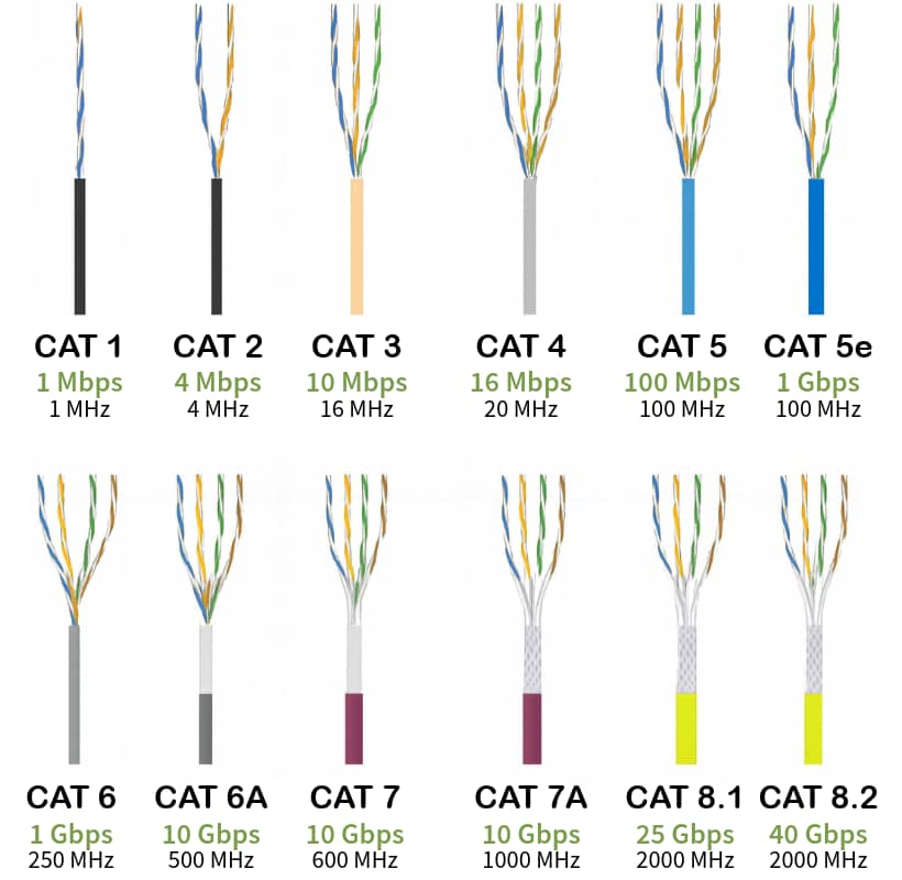
Cable types refer to the physical transmission medium. Think of them as the fundamental building blocks of your network connection. The three main cable types are coaxial, twisted pair, and fiber optic Ethernet cables. Cable categories are performance specifications that apply specifically to twisted pair cables. Think of Cat5e, Cat6, Cat6a, Cat7, and Cat8.

It’s like the difference between “vehicles” (types) and “sedan vs SUV” (categories within the car type).

Overview of Ethernet Cable Types

Before we dive into Cat5e vs Cat6 debates, you need to understand the three main cable types used in Ethernet networks:

Coaxial Ethernet Cables

Remember those thick yellow cables from the ’80s? That’s 10Base5 “Thicknet” coaxial cable. 10Base2 “Thinnet” was the thinner cousin. Both are essentially museum pieces now, but you might still find them lurking in really old installations.

Coaxial was great for its time. It had a simple concept: a single conductor surrounded by shielding. But it also had major limitations: shared collision domains, difficult troubleshooting, and maximum speeds that make dial-up look fast.

Twisted Pair Ethernet Cables

This is your bread and butter for modern networks. Four pairs of twisted copper wires in a plastic jacket. The twisting reduces electromagnetic interference – brilliant engineering from Alexander Graham Bell back in 1881 that still works today.

Twisted pair Ethernet cables come in two flavors:

  • Unshielded (UTP) – Standard for most office environments
  • Shielded (STP) – Extra protection against interference, essential in electrically noisy environments

H3: Fiber Optic Ethernet Cables

When copper hits its limits – because of distance, speed, or interference – fiber takes over. Light pulses through glass strands instead of electrical signals through copper.

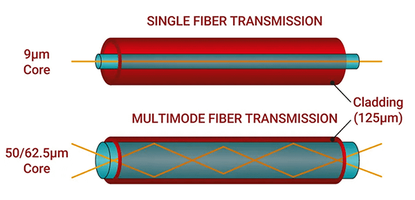
Single Mode Fiber uses one light path and reaches incredible distances. This is perfect for connecting buildings or campuses. Multimode Fiber uses multiple light paths, costs less than single mode, but works over shorter distances. Great for data center backbone connections.
Ethernet Cable Categories Explained

Since twisted pair dominates modern networks, let’s break down what those category numbers actually mean:

Cat5e (Category 5 Enhanced)

  • Speed: 1 Gbps
  • Bandwidth: 100 MHz
  • Distance: 100 meters

Cat5e has been around since the late ’90s, but don’t let that fool you. Cat5e still handles most office tasks without breaking a sweat. If your users aren’t complaining about slow network performance and you’re not pushing multi-gig applications, Cat5e gets the job done for a fraction of the cost of newer categories.

Cat6 (Category 6)

  • Speed: 10 Gbps up to 55 meters, 1 Gbps up to 100 meters
  • Bandwidth: 250 MHz
  • Distance: 100 meters (1G), 55 meters (10G)

Cat6 adds a plastic spline separator between wire pairs to reduce crosstalk. Perfect for WiFi 6 access points that need multi-gig backhaul connections. Just remember that 10G speed drops off after 55 meters, which becomes crucial for longer cable runs.

Cat6a (Augmented Category 6)

  • Speed: 10 Gbps
  • Bandwidth: 500 MHz
  • Distance: 100 meters

The enterprise sweet spot. Cat6a delivers full 10 Gbps performance over the complete 100-meter distance. Thicker and more expensive than Cat6, but it won’t leave you hanging when you need consistent high-speed performance over longer distances.

Cat7 (Category 7)

  • Speed: 10 Gbps
  • Bandwidth: 600 MHz
  • Only available shielded

Cat7 lives in standards limbo. ISO approved it, but TIA/EIA (the North American standards bodies) never blessed it. Some manufacturers developed proprietary connectors that aren’t compatible with standard RJ45 jacks. Unless you have very specific requirements, skip Cat7 and stick with Cat6a.

Cat8 (Category 8)

  • Speed: 40 Gbps
  • Bandwidth: 2 GHz
  • Distance: 30 meters

Cat8 is the data center speed demon. Built for 25G and 40G switch-to-switch connections where every millisecond counts. The cables are thick, expensive, and an overkill for typical enterprise deployments.
Pro Tip:

For enterprise WiFi deployments, Cat6a is your best friend. Modern WiFi 7 access points can push 2.5G or even 5G traffic back to your switch. Cat5e becomes the bottleneck, and Cat6’s distance limitations might bite you on longer runs. Cat6a gives you full 10G capability over 100 meters, providing plenty of headroom for current and future WiFi standards.

Cable Performance and Speed Capabilities

Cable specifications tell only part of the story. Real-world performance depends on installation quality, environmental conditions, and how well your equipment plays together.

For Enterprise Applications:

  • WiFi Access Points: Cat6a for multi-gig backhaul, future-proofing for WiFi 7
  • Switch Interconnects: Cat6a for 10G connections, Cat8 for 25G/40G in data centers
  • Server Connections: Fiber for backbone, Cat6a for 10G server NICs
  • Workstation Connections: Cat5e for basic office work, Cat6 for power users

Distance vs Performance Reality Check

Those maximum distance specs aren’t suggestions – they’re hard limits. A 105-meter Cat6 cable might link up, but you’ll get unpredictable performance. Network testing tools can identify these issues before they impact user experience.

Gaming Applications

Cat6 or Cat6a works great for gaming setups. The difference between Cat6 and Cat8 won’t turn you into a gaming god. Your internet connection speed and game server latency matter way more than cable category.

Pro Tip:

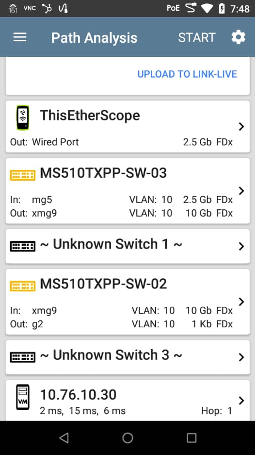
Don’t just chase maximum speeds – pay attention to your actual network bottlenecks. NetAlly’s Path Analysis feature in the EtherScope nXG can trace your connection from client to server, showing you exactly where performance drops off. You might discover that an expensive Cat8 cable isn’t fixing your real problem.
Choosing the Right Cable for Your Application

Enterprise Deployments:

Cat6a hits the sweet spot for most business networks. It supports current 10G equipment and leaves room for growth. The extra cost over Cat6 pays for itself when you don’t have to recable in three years.

Home Networks:

Cat5e handles typical home internet connections just fine. Even gigabit fiber connections won’t max out Cat5e capabilities. Spend your money on a better router instead.

Data Centers:

For data centers, use fiber for backbone connections and Cat6a or Cat8 for server connections depending on port speeds. The decision often comes down to equipment port density and power consumption.

Industrial Environments:

In industrial environments, shielded cables become essential around heavy machinery, motors, and electrical interference. The extra cost of the shielded twisted pair prevents mysterious connectivity issues that are a nightmare to troubleshoot.

Cable Compatibility and Performance

Good news – all Ethernet cable categories use standard RJ45 connectors, so newer cables work perfectly with older equipment from a physical connection standpoint.

That shiny Cat8 cable plugs right into your gigabit router without issues. But you’ll only get gigabit speeds because that’s what your router supports. The cable doesn’t magically boost your equipment’s capabilities beyond its design limits.

Cat7 compatibility gets tricky because of marketing confusion. The official Cat7 specification requires proprietary connectors (GG45 or TERA), but most cables labeled as “Cat7” in stores actually use standard RJ45 connectors. These RJ45-terminated cables perform somewhere between Cat6a and true Cat7 specs, but manufacturers market them as Cat7 anyway. It’s misleading, but that’s why you see “Cat7” cables that plug into regular Ethernet ports.

In mixed environments, your network runs at the speed of the slowest component. A Cat8 cable connected to Cat5e equipment still runs at Cat5e speeds. The weakest link in your chain determines overall performance.

Cable Length Limitations and Signal Quality

Cable length directly impacts network performance as signals weaken over distance. The magic number is 100 meters (328 feet) for twisted pair cables. Beyond that distance, signal strength drops below usable levels, causing packet loss, retransmissions, and connection failures.

Higher category cables don’t extend distance – they improve signal quality within that 100-meter limit. Cat7 and Cat6 both hit the same distance wall, though higher categories maintain better performance as you approach that limit.

Your internet speed isn’t determined by cable category if your current cable isn’t the bottleneck. Upgrading from Cat5e to Cat7 won’t boost gigabit internet – your service plan sets that limit.

Signal degradation follows basic physics. Higher frequency signals actually attenuate faster, which is why Cat6a and Cat8 need better construction to maintain performance over the full distance.

Cable Testing and Validation Methods

Professional cable testing catches problems that visual inspection misses. With NetAlly tools, you can save 60% of the time spent resolving network issues by identifying cable problems before they impact users.

Unterminated Testing uses Time Domain Reflectometry (TDR) – sending electrical pulses down the cable and measuring how long they take to bounce back. This reveals:

  • Cable length and distance to faults
  • Opens (broken wires)
  • Shorts between conductors
  • Split pairs (incorrect wiring standards)

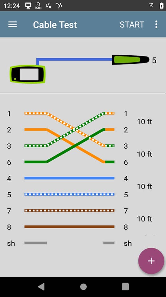
Terminated Testing requires wire view adapters at the far end but provides deeper validation:

  • End-to-end connectivity for every wire pair
  • Correct pin assignments (catching miswired connections)
  • Cable identification for documentation purposes
Performance Validation with LANBERT Media Qualification goes beyond basic connectivity by transmitting real network traffic at line rates. This tests whether your cable plant can handle the data speeds you’re paying for. It’s much more reliable than just checking electrical parameters against standards.

Troubleshooting Common Cable Issues

When your network starts acting up, knowing how to diagnose cable performance problems saves hours of headaches.

Split Pairs create one of the most frustrating problems. Your connectivity test passes, but performance is terrible. This happens when installers don’t follow T568A or T568B wiring standards properly, causing wire pairs to get “split” across different physical twisted pairs. The result? Crosstalk that destroys performance even though the cable technically “works.”

Downshifting occurs when your 10G-capable equipment stubbornly links at slower speeds due to marginal cable quality. The connection works, just not at the speed you’re paying for. Signal-to-noise ratio measurements help identify these problem cables before they impact users.

Length Problems sneak up on you because a 110-meter cable run might seem fine during initial testing. But it exceeds the 100-meter specification, causing performance to degrade gradually over time. These intermittent issues are particularly painful to diagnose because they don’t fail consistently.

Poor Connections at patch panels or jacks create the most unpredictable performance problems. A slightly loose connection might work fine under light load but fail when traffic increases. Cable testing with proper termination reveals these hidden troublemakers immediately.

Professional testing tools reduce problem escalations by 30% because they identify root causes instead of chasing symptoms. When you can prove the cable plant meets specifications, troubleshooting focuses on the real villains instead of endless cable swapping.

Advanced Cable Technologies and Future Considerations

Cat9 doesn’t officially exist yet, but the networking industry’s appetite for speed suggests it’s inevitable. If Cat9 emerges, it will likely push beyond Cat8’s 40 Gbps while staying within twisted pair’s 100-meter limit.

The real challenge isn’t speed – it’s physics. Higher frequencies mean more signal loss, requiring even better shielding and construction. Meanwhile, Power over Ethernet demands keep growing, data center speeds climb relentlessly, and edge computing needs reliable connections everywhere.

Market trends show fiber gaining ground for backbone connections while twisted pair evolves for end devices. The smart money isn’t on revolutionary changes but evolutionary improvements: better shielding, enhanced power delivery, and perhaps new connectors that maintain backward compatibility.

So, Which Cable Should You Choose?

Ethernet cable selection doesn’t have to be rocket science. Understand your application requirements, pick the right category for your performance needs, and test everything properly.

Cat5e still delivers solid performance for everyday connectivity tasks. Cat6a strikes the right balance for enterprise networks that need room to grow. Cat8 finds its home in data centers where massive bandwidth justifies the cost. Fiber steps in when copper simply can’t go the distance.

But remember – the best cable in the world won’t help if it’s installed poorly or never tested. That’s where professional testing equipment proves its worth by catching problems before they impact your users.

To validate your cable infrastructure like a pro, check out these NetAlly solutions:

  • LinkRunner AT 4000 – Smart network and cable tester for comprehensive diagnostics
  • LinkRunner 10G – Advanced multi-gig cable testing and performance validation
  • EtherScope nXG – Complete network analysis including cable testing and WiFi analysis

The sleekly designed WAX610W access point is purpose-built for hospitality, MDUs, and classrooms

September 3, 2025 – DENVER (CEDIA Expo 2025, Booth #3143) – NETGEAR® Inc. (NASDAQ: NTGR), a global leader in intelligent networking solutions designed to power extraordinary experiences, today announced the WAX610W, a compact, wall-mount Wi-Fi 6 access point designed to deliver high-performance, cost-effective connectivity for hospitality environments, multi-dwelling units (MDUs), and education settings. Created to simplify deployment and management while enhancing the guest and resident experience, the WAX610W combines enterprise-class performance with cloud-managed simplicity.

Delivering up to 1.8 Gbps of total throughput across dual bands, WAX610W helps to ensure fast, reliable wireless connectivity in high-density environments. It features one Gigabit PoE-In port for power and uplink, plus four Gigabit LAN ports to directly connect devices like IP phones, smart TVs, and projectors. With enterprise-grade security, seamless roaming, and remote management via NETGEAR Insight, it’s easy to scale and maintain and the optional Captive Portal enables a fully branded guest WiFi experience. The compact form factor and slim, elegant design fit easily into any interior while providing optimized omnidirectional coverage.

“Residential customers demand solutions that are reliable, yet unobtrusive,” said Nat Chidambaram, senior director, product management at NETGEAR. “The WAX610W access point–our smallest yet–blends seamlessly into its environment with an easily installed instant ceiling or wall mount. Managed by our Insight cloud platform, this AP is a quiet powerhouse.”

Reliable Coverage and Simple Installation

The WAX610W is compatible with client devices across Wi-Fi 4, Wi-Fi 5, Wi-Fi 6E, and Wi-Fi 7 on the 2.4 GHz and 5 GHz bands and supports mesh backhaul for flexible deployment. With NETGEAR’s Insight cloud management platform, IT teams can effectively segment traffic for administration, staff, guests, and IoT devices.

Purpose-built for modern hospitality and MDUs, the WAX610W connects to a Gigabit Ethernet switch to ensure maximum wired backhaul speed and features one PoE+ uplink port plus four additional Gigabit Ethernet ports for in-room connectivity. Bidirectional MU-MIMO and OFDMA enhance performance in dense client environments, enabling smooth streaming, rapid downloads, and responsive applications—key to improving guest satisfaction and reducing support tickets.

Compatibility and Security

The WAX610W is managed through NETGEAR Insight for enhanced security with centralized cloud and local control—no additional hardware controllers required. IT managers can deploy, monitor, and update networks remotely, standardize configurations across properties or campuses, and troubleshoot in real-time.  WPA2/WPA3 Enterprise and Personal security, OWE for open networks, and up to eight SSIDs per access point, ease the process of meeting compliance and segmentation requirements.

Compatible with other NETGEAR Insight Managed Access Points, the WAX610W integrates with both wired and wireless Instant Mesh networks to extend coverage quickly and cost-effectively. It works seamlessly with current and legacy client devices, ensuring wide compatibility and easing future upgrades.

WAX610W Technical Specifications

  • WiFi 6 Technology: Business class WiFi 6 performance (up to 1.8Gbps).
  • NETGEAR Insight Managed: For ease of centralized Cloud management, no additional hardware needed
  • Compatible with Insight Managed Access Points: Form a wired and/or wireless mesh network based on NETGEAR’s unique Instant Mesh technology
  • Multiple SSIDs: 8 separate wireless networks (SSIDs) can be used for administration, employees, guests, and IoT devices, including WiFi surveillance cameras, thermostats, door locks, and sensors
  • VLAN Support: Configure different VLANs on the LAN ports to prioritize the traffic like VoIP
  • Flexible Connections: One Gigabit Ethernet port with Power-over-Ethernet (PoE) for ease of deployment plus four Gigabit ports
  • Market-leading Support: 5-year warranty and next business day replacement 

Availability

The NETGEAR Insight Managed WiFi 6 Dual-band Gigabit PoE Access Point (WAX610W) is available now through NETGEAR’s authorized partners and resellers. For more information, visit https://www.netgear.com/business/wifi/access-points/wax610w/.

About NETGEAR, Inc.

Founded in 1996 and headquartered in the USA, NETGEAR® (NASDAQ: NTGR) is a global leader in innovative networking technologies for businesses, homes, and service providers. NETGEAR delivers a wide range of award-winning, intelligent solutions designed to unleash the full potential of connectivity and power extraordinary experiences. For businesses, NETGEAR offers reliable, easy-to-use, high-performance networking solutions, including switches, routers, access points, software, and AV over IP technologies, tailored to meet the diverse needs of small and medium enterprises. NETGEAR’s consumer products deliver advanced connectivity, powerful performance, and enhanced security features right out of the box, designed to help keep families safe online, whether at home or on the go. More information is available from the NETGEAR Press Room or by calling (408) 907-8000. Connect with NETGEAR: Facebook, Instagram and the NETGEAR blog at NETGEAR.com.


©2025 NETGEAR, Inc. NETGEAR and the NETGEAR logo are trademarks and/or registered trademarks of NETGEAR, Inc. and/or its affiliates in the United States and/or other countries. Other brand and product names are for identification purposes only and may be trademarks or registered trademarks of their respective holder(s). The information contained herein is subject to change without notice. NETGEAR shall not be liable for technical or editorial errors or omissions contained herein. All rights reserved.