


Breaking News

GLOBAL Wi-Fi NEWS bulletin

Your team is getting watched in two different ways right now, and neither one shows up in a security report.

The first is the network. The moment someone opens a laptop in a hotel, an airport, or a conference hall, their outbound traffic is visible to anyone else watching that network.

The second happens everywhere, including on the network you own. The sites your team visits are quietly collecting: Location trackers, mail trackers, data brokers, and ad networks build profiles in the background on every single visit.

We have had tools for the first problem for years. The catch is that most of them only work when the user remembers to turn them on. They forget. They skip it on fast hotel Wi-Fi. They turn it off when it slows something down.

That gap, between “we have a tool for that” and “protection is actually running,” is where traffic gets intercepted and users get profiled.

SecureTransit closes it.

What SecureTransit does

SecureTransit is endpoint privacy, enforced as policy. It does two things.

It encrypts outbound traffic before it leaves the device. Every time your team connects from a hotel, an airport, or a conference, they are on a network you do not own, and traffic on those networks can be observed and intercepted. SecureTransit encrypts it at the device, so what crosses the wire is unreadable to anyone watching locally.

It blocks trackers at the source. Location trackers, mail trackers, data brokers, and ad networks get cut off before data ever leaves the device. This one applies on any network, from the office to home network to hotel Wi-Fi.

SecureTransit ships inside the DNSFilter Roaming Client, the same lightweight agent you already use for filtering and for user activity intelligence through CyberSight. There is no second agent to deploy and no second console to learn.

Admins set the mode per organization or per device: Always-On, Manual, or Disabled. Credentials are provisioned and managed server-side, so your users never configure anything. That means they cannot misconfigure anything, and in Always-On mode, they cannot opt out.

SecureTransit is currently in beta and is available in our existing two-week free trial.

Login or start your free trial today.

“Doesn’t DNSFilter already block trackers?”

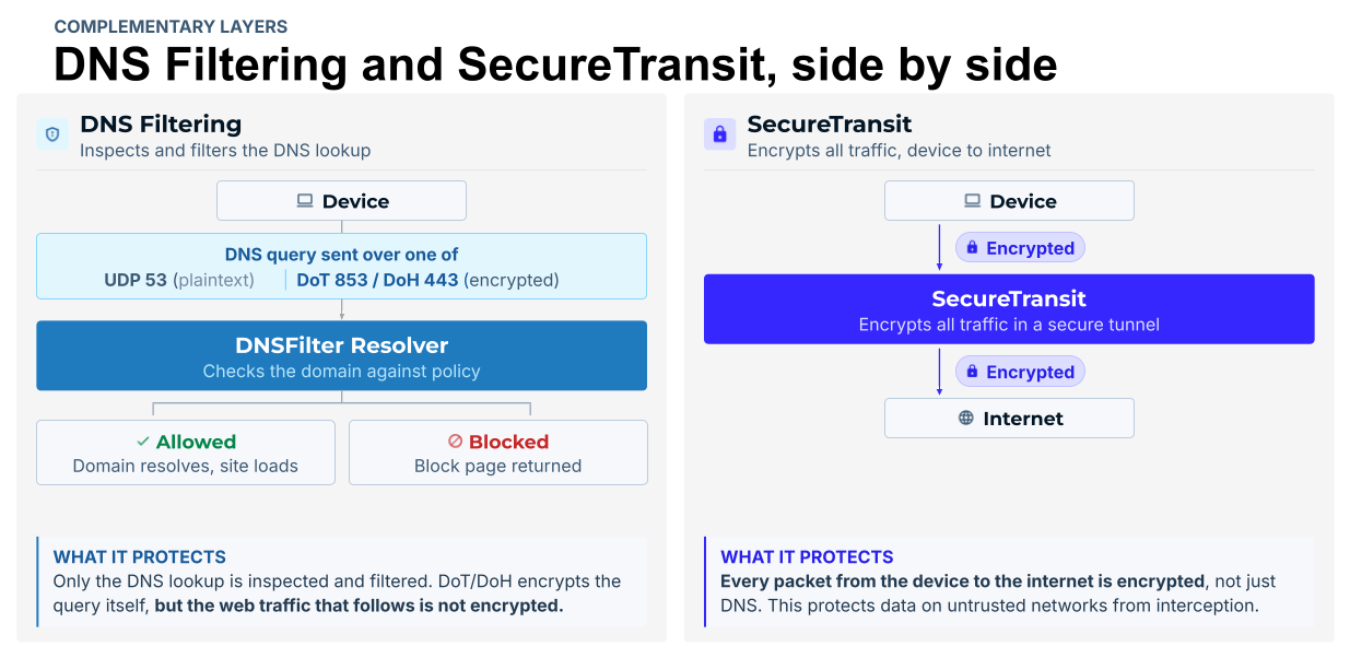
Fair question, and yes, at the DNS layer. DNS filtering blocks trackers during DNS resolution, before a connection is ever made, and it runs everywhere your Roaming Clients run.

SecureTransit blocks the tracker connection at the source, as traffic passes through the tunnel. That catches what DNS-layer blocking alone cannot, and it encrypts everything else along the way.

One distinction worth making: DNS-over-TLS and DNS-over-HTTPS encrypt the DNS query itself, but everything that comes after that query is still in the clear. SecureTransit encrypts the whole path, device to internet.


The two run as complementary layers with a graceful fallback. If the tunnel is disconnected or disabled, the device falls back to DNS-layer tracker filtering. Protection degrades. It never disappears.

Privacy from outsiders, not from your security team

This is the part I want to be clearest about, because “privacy” can sound a lot like “a place my users go that I cannot see.”

SecureTransit shields users from local-network observers and third-party trackers. It never shields them from your own admins. You keep the same DNS query visibility you have today, so there are no blind tunnels and no reporting gaps. Your users get privacy from outsiders, and you keep the audit trail.

One agent, three capabilities

With SecureTransit, the DNSFilter Roaming Client delivers three distinct capabilities through a single lightweight agent:

  • Filtering. DNS-layer protection through our global Anycast network (Classic mode) or local interception through DNS PreCheck, depending on your deployment
  • CyberSight. User behavior analytics at the endpoint, surfacing the applications and services your users are actually running, including the locally installed AI tools that DNS-layer analysis cannot see
  • SecureTransit. Encrypted outbound traffic and tracker blocking, enforced as admin-controlled policy

One deployment. Three capabilities. One place to manage all of them.

Turn it on where the exposure actually is

SecureTransit is a per-device add-on. You license it where the risk lives instead of paying for every endpoint in the building.

For most teams, that is a short list: The people who travel, the executives, the fully remote staff, and honestly, the users who keep failing your phishing simulations. If you are running 100 Roaming Clients and 10 of those users are the ones genuinely working off untrusted networks, you cover those 10.

Cost scales with exposure, not headcount.

For MSPs, that is what makes it sellable. SecureTransit runs inside the same multi-tenant dashboard you already use, so your techs deploy it without adding a vendor, a console, or a new workflow. This way, you can lead the conversation around privacy with: “Privacy is enforced as policy on every device that needs it.”

Why we built it as policy

Enforcement has been a weak point for structural reasons more than technical ones. Most privacy tools are separate products with a separate agent, a separate console, and a separate vendor. That means another deployment to manage, another set of credentials to maintain, and a dependency on users to actually connect.

Every one of those is a place where it can quietly fail. The tool sits in a different workflow than your filtering policy. There is no way to tie enforcement to the organizational hierarchy you already manage. And when a user is off-network on a connection you do not control, you have no way to confirm anything is running at all.

We built SecureTransit for managed environments, where policy enforcement, not user behavior, is the security model.

DNSFilter blocks the threats. SecureTransit handles the privacy. Your data should be yours: On hotel Wi-Fi, on the office network, and inside every site your team visits.

Trying SecureTransit

SecureTransit entered beta on Aug. 17, 2026, and it is available today on the Windows Roaming Client, version 3.7 and up. Support for our other platforms is coming.

You can test it today in our 14-day trial. Then go look at how many trackers it blocked for those people in two weeks. That number tends to be the whole argument.

Every embedded product that needs to talk to the outside world starts with the same question: which radio?

For a long time, the answer was simple, because the product usually only needed to do one thing. A fitness tracker needed BLE to sync with a phone. A factory sensor needed LTE to report back to a server. One job, one radio, done.

Today the answer is more complicated, and more consequential. Because the right answer isn’t just a technical choice, it’s arguably the highest-stakes decision you’ll make on the entire product. 

Get it right and you have a device that works reliably in the field for a decade. Get it wrong and you’re looking at a board respin, a recertification cycle, and a failure mode your customers will find before you do. And unlike most decisions in a product’s life, this one is nearly impossible to undo once silicon is chosen.

So the answer is no longer “which radio.” It’s increasingly “which radios, in what combination, and have you thought through everything that combination is going to cost you — in power, in board space, in firmware complexity, and in the years of maintenance that follow.”

That’s what this article is about.

Why Connectivity Decisions Matter Early

Most engineering decisions in a product’s lifecycle can be revisited. A firmware bug gets patched over the air. A mechanical tolerance gets adjusted in the next molding run. Even a processor choice, painful as it is to change, can often be recovered through a firmware port and board revision, especially when the software is built on a portable platform such as Zephyr.

Radio selection doesn’t work that way, because a radio isn’t really one decision. Radio selection is a stack of decisions that get poured into the board layout and never separated again.

Choosing BLE plus Wi-Fi plus UWB means choosing a chipset (or combination of chipsets) that supports that exact set, an antenna configuration that gives each radio enough isolation to not desensitize the others, a power budget that assumes certain radios are off most of the time, and a certification path that covers every one of those radios in every region the product ships to.

Each of those downstream decisions assumes the radio set is fixed. If a customer asks six months into development for UWB ranging that wasn’t in the original spec, the answer usually isn’t “we’ll add a UWB chip.” It’s closer to “we need a new board revision, a new antenna layout, a new RF coexistence study, and a new certification cycle” — months of work triggered by a requirement that, on paper, looks like adding one part to a BOM.

The reverse is just as costly. Overprovisioning — adding LTE “just in case,” or UWB because a competitor’s spec sheet has it, means paying for certification, power budget, and board space for a radio that may never get used. On a product shipping in volume, that’s not a rounding error; it’s margin, gone, on every unit, for the life of the product.

Understanding the Role of Each Radio

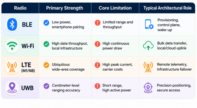
Once the product features are clear, the next step is to match each feature to the radio that solves it, and resist the temptation to make one radio do a job it wasn’t built for. Each of these technologies has a narrow zone (sweet spot) where it’s the ideal answer,  a much wider zone where it’s just ok, and a wide zone where it’s the wrong choice.

1. Bluetooth Low Energy (BLE)

BLE is the default for short-range, low-power interaction between a device and a phone. It’s good at presence detection in a loose sense, pairing, small data exchanges, and running for years on a coin cell. 

What it’s not good at is precision. BLE signal strength (RSSI) can tell you roughly whether something is near or far, but “roughly” can mean several meters of error depending on the environment. A closed door, a person’s body, a metal cabinet can all shift the reading enough to make an access-control decision unreliable. BLE answers “is a known device: somewhere nearby vs at this specific point in space.”

2. Ultra-Wideband (UWB)

UWB exists for the question BLE can’t answer: precise distance and, with the right setup, direction. Using time-of-flight measurements across a wide spectrum band, UWB can resolve position to within centimeters, largely independent of the interference and multipath issues that make BLE’s RSSI unreliable indoors. 

This is why it has become the standard for secure ranging, proving a credential is physically at the door, not just somewhere in the building. It is used for spatial awareness use cases like asset tracking or hands-free unlock. 

The tradeoff is power and cost. UWB radios draw more current than BLE and add bill-of-material cost, so they show up only when the product genuinely needs spatial precision, not as a general-purpose connectivity radio.

3. Wi-Fi

Wi-Fi is the high-bandwidth, infrastructure-dependent option. It’s the right choice when a device needs to move real data, such as firmware updates, video, logs, large configuration syncs, and when it can rely on existing network infrastructure being present and powered. 

Wi-Fi’s weaknesses are exactly its dependencies: it needs an access point in range, it draws meaningfully more power than BLE (especially when maintaining an active connection), and it inherits whatever reliability problems exist on the local network. A device that only has Wi-Fi has no story for “what happens when the network is down,” which is precisely the gap LTE fills.

4. LTE

LTE (or cellular more broadly) is the answer to “this device needs to reach the outside world regardless of what local infrastructure does or doesn’t exist.” It doesn’t depend on a router, a switch, or anyone’s IT configuration. It depends on a SIM and a cell tower. That independence is also its cost. 

Cellular modules are more expensive, carry recurring data plan costs, and consume more power than any of the other three radios discussed here. LTE earns its place on a board when a device going silent because someone unplugged a switch is unacceptable.

5. Thread

Thread is worth understanding separately from BLE and Wi-Fi, even though it often ships on the same combo silicon. It’s a low-power, IPv6-based mesh networking protocol built specifically for IoT devices. Where BLE connects a device to a phone and Wi-Fi connects it to the internet, Thread connects groups of devices to each other and to a border router, forming a self-healing mesh that doesn’t depend on a central access point staying online.

Its sweet spot is dense deployments of battery-powered nodes that need to communicate reliably without individually maintaining a Wi-Fi connection — think building sensors, industrial monitoring arrays, or smart lighting grids.

Many modern Wi-Fi combo chips from Silicon Labs, Nordic, and NXP already include Thread support alongside BLE, so the incremental BOM cost is often minimal. The decision is less about hardware and more about whether your application architecture can take advantage of the mesh.

6. Zigbee

Zigbee occupies similar territory to Thread — low power, mesh networking, short-range IoT — but with a longer installed base and deeper penetration in industrial and building automation markets. Where Thread is IP-native and designed with future interoperability in mind, Zigbee has decades of deployed infrastructure behind it, particularly in smart energy, HVAC, and industrial control environments where ripping out existing infrastructure is not an option.

Like Thread, Zigbee frequently ships bundled on combo chips alongside Wi-Fi and BLE. For products intended for environments where a Zigbee coordinator is already present or where the customer base expects Zigbee compatibility, it earns its place without adding significant BOM cost. For greenfield deployments with no existing Zigbee infrastructure, Thread’s IP-native architecture is generally the more future-proof choice.

Summary Pattern — Which Radio Answers Which Question:

  • BLE answers presence and pairing
  • UWB answers precise location
  • Wi-Fi answers high-bandwidth data movement
  • LTE answers infrastructure independence
  • Thread answers low-power mesh networking in IPv6-native environments
  • Zigbee answers mesh networking in established IoT and building automation ecosystems

There’s a lot more interesting comparisons and contrasts in our previous post – UWB vs BLE vs Wi-Fi for Indoor Location Tracking.

Common Multi-Radio Architectures

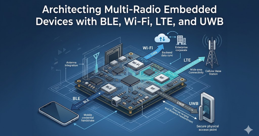
In practice, most multi-radio products fall into a handful of recognizable patterns, and which pattern fits depends less on what the radios do individually and more on how tightly they need to be coordinated.  Here are four common multi radio approaches:

i) Single SoC, Multiple Integrated Radios.

Many modern wireless SoCs bundle BLE and Wi-Fi (and sometimes Thread or Zigbee) into a single chip with shared RF front-end logic. This is the simplest path when the radio set aligns with what the SoC vendor offers: one part number, one toolchain, one set of drivers, and coexistence handled to varying degrees by the vendor’s firmware. 

The constraint is that the product’s radio requirements must fit within what the SoC was designed to support. If the access controller needs UWB and the SoC doesn’t include it, this pattern stops being an option for that radio, no matter how convenient it is for the other two.

ii) Host Processor Plus Discrete Radio Modules

Here, a main application processor (often running Linux or a heavier RTOS) talks to separate modules for each radio it doesn’t have natively — a Wi-Fi/BLE combo module over SPI or UART, a UWB module over SPI, an LTE module over a serial AT-command interface. 

This is the most flexible pattern and the one that scales best to four radios, because each module can be sourced, certified, and swapped somewhat independently. The cost is integration complexity: every module has its own driver and power sequencing requirements, and the host processor has to arbitrate between them — including managing which radios can be active at the same time without desensitizing each other.

iii) Tiered Architecture with a Connectivity Co-Processor

In more constrained designs, a small microcontroller is dedicated solely to managing radios — handling BLE and UWB, for instance — while a separate, more capable processor handles the application logic and interfaces with Wi-Fi and LTE. 

This splits the problem along power and real-time boundaries: the radio co-processor can stay in a low-power state managing BLE advertising or UWB ranging windows, while the main processor only wakes for higher-level tasks. 

It adds a second processor and an inter-processor communication layer, but it can meaningfully reduce overall power draw in products where BLE or UWB need to be active far more often than Wi-Fi or LTE.

iv) Cellular-Centric Architecture

For products where LTE is the primary link and everything else is secondary — remote sensors with a BLE configuration interface, for example — the LTE module often becomes the de facto main processor, running application logic on its embedded MCU and treating BLE as a peripheral feature rather than a full radio stack. 

This minimizes part count and cost but constrains how much local processing or radio coordination the product can do, since the cellular module’s MCU is typically far less capable than a dedicated application processor.

Engineering Challenges in Multi-Radio Designs

Picking the right radios and the right architecture pattern gets a design to the starting line. What happens when four radios have to share one board and operate at the same time is where most of the real engineering effort goes, and where most of the surprises show up late.

i) RF Coexistence

BLE, Wi-Fi, and parts of UWB all operate in or near the 2.4 GHz band, and when they’re on the same board, they interfere with each other. A Wi-Fi transmission can desensitize a BLE receiver sitting a few millimeters away on the same PCB, causing dropped connections or missed packets that have nothing to do with either radio’s actual range. 

Solving this isn’t a matter of picking good chips; it requires coexistence schemes — time-division arbitration between radios, frequency planning, and sometimes dedicated coexistence signaling lines between chips — that have to be designed in from the start and validated with real RF measurements.

ii) Antenna Placement and Isolation

Four radios usually means four antennas (or, at minimum, several), and on a small board there often isn’t a clean way to place them all without some degree of mutual coupling. An antenna tuned for UWB’s wide bandwidth has different placement and ground-plane requirements than a BLE antenna, and putting them too close together degrades both. 

This is one of the reasons radio decisions can’t be deferred. Antenna placement is decided at board layout, and a layout designed for three antennas doesn’t have a clean path to “just add a fourth” without redoing the RF design around it.

iii) Power Budget and Duty Cycling

Each radio has a different power profile, and the difference between “available” and “active” matters enormously. UWB ranging and active Wi-Fi connections can draw an order of magnitude more current than BLE in a low-power advertising state. 

A device that needs to run on battery for months, but also needs to maintain a UWB ranging session for security, has to carefully duty-cycle which radios are active when — UWB only during the ranging window, Wi-Fi only during sync windows, LTE only as a fallback — and the firmware managing that duty cycling has to be correct, because a bug that leaves one radio on continuously can turn a multi-month battery life into a multi-day one.

iv) Certification Across Radios and Regions

Every radio on the board needs regulatory certification, such as FCC and CE, for every region the product ships to, and these certifications aren’t independent of each other. Adding a radio, or even changing antenna placement for an existing one, can require recertifying the whole RF system. 

For a product shipping to multiple regions, this multiplies: four radios across, say, North America, Europe, and a few other markets can mean a dozen or more separate certification efforts, each with its own timeline and cost, and each one that has to be redone if the RF design changes after the fact.

v) Software Abstraction

The application layer generally shouldn’t need to know whether a connection came over Wi-Fi or LTE, or whether a presence signal came from BLE or UWB. But someone has to build that abstraction, and it has to handle radios with very different connection models, latencies, and failure modes underneath a single interface. 

Getting this wrong creates products where switching between radios (say, falling back from Wi-Fi to LTE when the network drops) introduces visible delays, dropped data, or inconsistent behavior that the end user experiences as the product simply being unreliable.

None of these is a separate workstream that can be solved in isolation and then assembled; they have to be reasoned about together, from early in the design, by people who understand how each piece constrains the others

Where the Industry Is Heading

A few trends are starting to reshape how these tradeoffs get made, and most of them point toward pushing more of the multi-radio complexity off the board designer’s plate and into silicon, software stacks, and standards that didn’t exist a few years ago.

1. Combo Chips are Absorbing More Radios.

The first wave of combo chips merged BLE and Wi-Fi because they were the most common pairing and shared enough RF infrastructure to make integration worthwhile. The newer wave is starting to add UWB into that mix, and a few vendors are exploring tighter integration with cellular as well. 

As this continues, some of the products described earlier, like the access controller that needs BLE, UWB, Wi-Fi, and LTE, may eventually be built around two chips instead of four, with much of the coexistence work handled inside the combo part rather than designed from scratch on the board.

2. Coexistence is Moving from Board-Level Workaround to Chip-Level Feature

Coexistence between radios was something board designers solved after the fact — adding coexistence signaling lines between separately-sourced chips, tuning time-division schedules in firmware. 

Newer silicon is starting to build coexistence arbitration in as a designed feature, with chips that are aware of each other’s activity and negotiate airtime automatically rather than requiring a board-level protocol to be designed and validated independently for each combination of parts.

3. UWB is Becoming Less of a Specialty Add-on

UWB’s role was usually kept as a radio added only when a product specifically needed that capability. As UWB chips get cheaper and smaller, and as ecosystems (particularly around digital car keys and access control) standardize on UWB for proximity verification, it’s increasingly showing up as a default inclusion in certain product categories. This shifts UWB from “the radio you add if you need precise ranging” toward “the radio you include by default in this category, the way BLE became default a decade ago.”

4.  Software Abstraction Layers are Maturing

The idea of a connectivity manager — a software layer that gives the application a single “connected/disconnected” interface regardless of which radio underneath provides it — isn’t new, but until recently most of these were built in-house, per product, with all the inconsistency that implies. 

Some RTOS vendors and silicon vendors are starting to ship more complete connectivity stacks as part of their SDKs, covering radio selection, fallback logic, and power state management together. This is reducing the amount of glue code a multi-radio product needs to write from scratch.

Closing Thoughts

BLE, Wi-Fi, LTE, and UWB modules are well-documented, widely sourced, and individually well understood. What’s hard is the part that doesn’t show up on any single chip’s datasheet: how they behave once they’re sharing a board, a power budget, and an antenna layout — and how that combination holds up across years of firmware updates and certification cycles in the field.

That’s the gap between a product that works in a lab demo and one that works on a loading dock in winter, on a battery that has to last a year, and on a network connection that drops without warning. Closing that gap isn’t a single decision. It’s dozens of smaller ones, made early, by people who’ve seen where these designs tend to go wrong before they go wrong.

This is the kind of problem embedUR works on with clients — taking a product from “here’s what it needs to do” to a board and firmware architecture that holds up once it’s shipped, across the radios, the power budget, and the years of updates that follow.

If you’re working through a multi-radio architecture decision and want a second set of eyes before it’s locked into silicon, talk to embedUR’s connectivity team. The earlier this conversation happens, the more options stay open.

Energy efficiency has become a key differentiator for hotels and multi-dwelling units (MDUs). Rising utility costs, ambitious sustainability goals, and increasing guest expectations are driving property owners to address this by investing in smarter building automation. According to the International Energy Agency’s (IEA) Energy Efficiency 2025 report, buildings account for around 30% of global energy demand, making hotels and MDUs two of the largest opportunities for improving operational efficiency.

For developers building next-generation connected buildings, meeting this challenge requires creating scalable energy-management solutions. This starts with secure, low-power endpoints that communicate reliably across an entire property. Z-Wave Long Range provides the wireless foundation to connect these endpoints at scale, enabling hotels and MDUs to sense, connect, and respond intelligently.

Why Energy Management Needs Smarter Endpoints

Energy management is becoming a broader priority across the connected-device ecosystem. In smart homes, for example, Matter Energy Management is expanding how devices can share energy information and coordinate their operation. Hotels and MDUs take this challenge to a different scale, where wireless coverage, endpoint scalability, and long-term operation become critical.

Today’s Hotels/MDUs already contain connected thermostats, occupancy sensors, smart locks, lighting controls, and environmental sensors. But many energy-saving opportunities remain untapped because these devices often operate independently rather than as an intelligent system.

Consider a hotel room after a guest checks out. Without occupancy awareness, HVAC systems may continue conditioning an empty room, lights remain on unnecessarily, and housekeeping receives no automated indication that the room is vacant. Similar inefficiencies occur in apartment buildings, where common-area lighting, environmental controls, or vacant units continue consuming energy regardless of actual occupancy.

Energy Management Automation

Solving these problems requires endpoints that can securely exchange information, respond locally to occupancy changes, and scale across hundreds or thousands of devices without increasing deployment complexity.

In other words, scalable energy management starts with scalable wireless endpoints.

Why Z-Wave Long Range for Energy Management Devices?

Hotels and MDUs present unique connectivity challenges. Devices are distributed across multiple floors, concrete walls reduce signal propagation, and many endpoints must operate on batteries for years with minimal maintenance.

Z-Wave Long Range addresses these challenges by extending reliable Sub-GHz communication while supporting significantly larger endpoint populations than traditional residential deployments. The combination of long-range communication, low-power operation, and certified interoperability enables occupancy sensors, thermostats, lighting controls, leak detectors, and smart locks to work together as a coordinated energy-management system.

Similarly, certified interoperability allows manufacturers to develop products that integrate into an established ecosystem, giving building operators greater flexibility when selecting devices while reducing deployment risk and protecting long-term infrastructure investments.

For developers, this means building products that can support both today’s installations and tomorrow’s larger, more intelligent properties without redesigning the underlying wireless architecture.

Designing Better Energy-Management Devices with Z-Wave Long Range

Building intelligent endpoints requires more than selecting a wireless protocol. Developers must balance battery life, security, installation simplicity, application complexity, and long product lifecycles within a single device.

Silicon Labs addresses these challenges through a combination of low-power wireless hardware, integrated security, certified software, and a comprehensive development ecosystem. The EFR32ZG28 demonstrates how these capabilities come together for next-generation Z-Wave Long Range products.

One practical challenge is commissioning hundreds of devices across a large property. The EFR32ZG28 combines Z-Wave Long Range connectivity with optional Bluetooth® Low Energy, enabling installers to use familiar mobile workflows for device commissioning and servicing while maintaining robust connectivity through the Z-Wave network. Part of the Z-Wave 800 family, the ZG28 combines energy-efficient operation, strong RF performance, long-range connectivity, and industry-leading security.

Connected thermostats, locks, and environmental sensors may remain deployed for more than a decade while controlling critical building functions, making security a non-negotiable aspect of development. Secure Vault™ provides hardware-rooted protection for device identities, cryptographic keys, secure boot, and firmware integrity, helping developers build products designed for long-term operation and evolving cybersecurity requirements.

Application complexity also continues to grow. Modern energy-management devices increasingly combine sensing, user interfaces, local control algorithms, firmware updates, and multiple communication interfaces. The EFR32ZG28 provides additional memory and processing resources that give developers room to expand application functionality without requiring a hardware redesign as products evolve.

Edge processing is becoming equally important for practical energy-management applications. Rather than transmitting every sensor event to the cloud, endpoints can locally distinguish between brief movement and sustained room occupancy before triggering HVAC or lighting adjustments. This reduces unnecessary network traffic while enabling faster responses to changing conditions. Integrated AI/ML acceleration provides additional headroom for these evolving endpoint functions as occupancy sensing and environmental monitoring become more sophisticated.

Energy Management Workflow

Accelerating Commercial Energy Management Product Device Development

Developing a commercial energy-management product involves considerably more than selecting a wireless SoC. Engineering teams must integrate protocol software, implement security, complete certification, optimize battery life, validate wireless performance, and maintain products throughout long deployment lifecycles.

Developers building energy-management applications can accelerate their workflow using Silicon Labs’ Simplicity Studio, a unified development platform that brings together SDKs, network analysis, and energy-profiling tools in one place. By handling the complexity of foundational technology integration, Simplicity Studio makes it possible for engineers to focus on building differentiated features that deliver real, measurable value to property operators.

Building the Next Generation of Intelligent Buildings

The next phase of energy management will be defined not by the number of connected devices, but by how intelligently they work together to understand occupancy, anticipate energy demand, and adapt building operations in real time. As buildings continue to evolve, developers will face new questions. How can endpoints make more decisions locally while maintaining ultra-low power consumption? How can thousands of connected devices remain secure throughout decade-long deployments? How can building systems become more autonomous without increasing complexity for installers and operators?

The answers to these questions will shape the next generation of intelligent buildings, and the wireless endpoints being designed today will play a central role in enabling that future.

Conditional Approval supports continued U.S. deployment while reinforcing Zyxel’s commitment to trusted, secure networking solutions

Anaheim, California, (Aug. 25, 2026) — Zyxel Communications today announced that its Wi-Fi 7 gateways (EE4210 and EE6610) and 5G NR Indoor Router (NR5331) have received Conditional Approval, exempting these products from the Federal Communications Commission’s (FCC) Covered List through February 3, 2028.

The Conditional Approval enables service providers and businesses to continue importing, purchasing and deploying these Zyxel broadband solutions in the United States during the approval period.

As broadband providers navigate evolving security and regulatory requirements, Zyxel remains focused on providing customers with trusted, flexible technology choices that support their ability to expand and modernize their networks.

“Trust and security have always been fundamental to how we develop and support our products,” said Edmund Chu, Executive Vice President at Zyxel Communications. “This Conditional Approval provides additional assurance to our customers as they plan their broadband deployments. We will continue investing in product security, long-term support and reliable connectivity that helps our customers confidently grow their networks.”

The Conditional Approval covers three Zyxel solutions designed for next-generation broadband connectivity as part of Zyxel’s broader portfolio of networking solutions:

EE4210: A tri-band BE10000 Wi-Fi 7 gateway with 2.5GbE WAN/LAN connectivity, designed to deliver high-performance connectivity for next-generation broadband services and connected homes.

  • EE6610: A tri-band BE19000 Wi-Fi 7 gateway with 10GbE WAN/LAN connectivity, built to support multi-gigabit broadband services and high-performance connected-home applications.
  • NR5331: A 5G NR indoor router designed for flexible fixed wireless broadband deployments and POTS replacement over 5G

A Continued Commitment to Network Trust

The FCC added certain foreign-produced routers to its Covered List in March 2026 as part of broader efforts to protect U.S. communications infrastructure. Products that receive Conditional Approval through the applicable federal review process are exempt from the Covered List and its associated restrictions for the duration of that approval.

Zyxel maintains a comprehensive approach to product and network security, including ongoing firmware maintenance, vulnerability management, publicly available security advisories and lifecycle support.

Beyond regulatory compliance, Zyxel is committed to helping service providers and businesses build networks they can trust. Zyxel’s comprehensive portfolio spans PON/XGS-PON, Wi-Fi 6 and Wi-Fi 7, 5G FWA, PTMP, Switching, Security, Wireless Access and Cloud-Managed Networking.

For more information about Zyxel and its broadband and networking solutions for service providers and businesses, visit the Zyxel Communications website and follow us on YouTube, Facebook, X and LinkedIn.

About Zyxel:

Zyxel Communications delivers technological innovations and has connected the world to the internet for more than 35 years. Whether establishing access through fixed or mobile broadband solutions, Zyxel Communications offers a comprehensive and flexible portfolio that helps service providers stay ahead of the competition.

If your infrastructure predates 2016, you built it around a simple mental model: more speed means a bigger, faster version of the same thing. That model breaks completely once you cross into 25G-and-up territory. The lane architecture changes, the optics change, the error-correction requirements change, and the failure modes change. None of it is a firmware update away.

This is the first post in a series on high-speed Ethernet. Before we get into transceivers, polarity, and FEC in detail, here’s the architecture you need to understand first.

Lanes Are the Unit That Matters, Not “Speed”

A lane is a single electrical or optical path running at a fixed signaling rate. Everything above 10G is built by bundling lanes, not by cranking up a dial.

  • 10G = one 10G lane
  • 25G = one 25G lane (802.3by, ratified 2016)
  • 40G = four 10G lanes (802.3ba)
  • 100G = four 25G lanes (802.3bm, and later 802.3cd variants)

This is where a lot of confusion starts, because “four lanes” doesn’t mean the same physical thing across every variant. 40GBASE-LR4 and 100GBASE-LR4/ER4 genuinely do run multiple wavelengths over a single strand of single-mode fiber using CWDM (Coarse Wavelength Division Multiplexing – several wavelengths spaced far enough apart that the lasers don’t need precise temperature control, combined and split inside the transceiver itself) , that’s true WDM. But the short-reach variants most data centers actually deploy, 40GBASE-SR4 and 100GBASE-SR4, use parallel fiber: four separate transmit/receive fiber pairs inside one MPO/MTP connector, each carrying its own lane on multimode fiber. No wavelength multiplexing involved. Mixing these two models up is one of the most common misunderstandings people carry into their first 100G deployment, and it matters the moment you’re troubleshooting a link and trying to figure out whether you’re chasing a wavelength problem or a fiber-pair problem. In short, SR4 and LR4 both say “4,” but one means four fibers and the other means four colors , which is exactly what determines whether a bad link is a fiber-pair problem or a wavelength problem.

And for anyone about to ask “what about 50G” , 50G doesn’t scale the way 40G and 100G do. Those two bundle more lanes at a fixed per-lane rate , four 10G lanes and four 25G lanes respectively. Single-lane 50G (802.3cd) keeps one lane and changes the modulation instead, using PAM4 signaling (four amplitude levels per symbol, carrying two bits per signaling interval) on one lane to hit 50 Gbps, versus four lanes of NRZ signaling (the older two-level scheme that carries one bit per interval) for 100GBASE-SR4. Different modulation, different lane count, different electrical characteristics. It’s architecturally its own thing, not a stepping stone between 25G and 100G.

Why 40G Isn’t Dead

Speed adoption moves from the core outward , financial trading floors and hyperscalers push 100G first, everyone else follows on a slower curve. Right now 40G and 25G are sitting in the price/performance sweet spot for campus aggregation, hospital networks pushing real-time imaging and patient data, and on-prem data centers that don’t have hyperscaler budgets or hyperscaler traffic volumes.

Two practical reasons 40G survives:

  1. The server is usually the bottleneck before the link is. Swapping a NIC from 40G to 100G does nothing if the application, the PCIe bus, or the storage backend can’t feed it.
  2. QSFP+ (40G) modules are mechanically compatible with QSFP28 (100G) ports. You can often upgrade a core switch to 100G and keep 40G distribution switches hanging off it , assuming the switch ASIC and firmware actually support mixed-rate operation, which isn’t universal and is worth confirming with your vendor before you assume it. Where it works, it lets you upgrade the core surgically instead of ripping out the whole plant at once.


25G: The Base Unit, and Why It’s Sensitive

25G per lane became the industry’s building block because the math scales cleanly , 4x25G gets you 100G, 4x100G gets you 400G. It’s also economically attractive: 25G optics have come down in price enough that they’re now routinely deployed at scale in leaf-spine fabrics, commonly in a 48x25G-server / 6x100G-uplink rack layout, all running the same underlying lane technology.

The catch is signal tolerance. A 25G lane is far less forgiving of loss and reflection than a 10G lane running over the same physical plant.

Pro Tip:

Pro tip: OM4 multimode fiber that’s carried 10G cleanly for years is not automatically ready for 25G or 100G-SR4. A connector that’s slightly dirty or has minor end-face damage will barely register as a problem at 10G and will cause consistent packet loss at 25G. Clean and inspect your connectors, and test the actual link before cutover , don’t assume a fiber plant “passes” just because it’s been quiet at a lower speed.

100G Doesn’t Get New Problems, It Gets 25G’s Problems, Four Times Over

Because 100G-SR4 is four independent 25G lanes, any marginal condition that a single 25G lane tolerates gets multiplied across the link. A cabling plant that was “good enough” for 40G (4x10G, NRZ, more forgiving) can fail outright at 100G with random packet loss and flapping links , not because anything changed, but because the margin for error that existed at 10G-per-lane never existed at 25G-per-lane.

Two specifics worth knowing before you deploy:

FEC often has to be configured manually, not negotiated. For optical modules using clause 82/91 encoding, FEC is typically a manual setting on both ends of the link , mismatched FEC settings between two devices is a classic cause of a link that “should work” but doesn’t. (Backplane/copper links using clause 73 autonegotiation are the exception , FEC there can be negotiated automatically.) Check both ends explicitly; don’t assume. (Note these clause numbers are section numbers within IEEE 802.3, not vendor settings.)

There’s no auto-MDIX equivalent on fiber. Auto-MDIX is a copper concept. On fiber, TX/RX polarity has to be managed correctly across the MPO cassette, trunk, and patch cords, and getting it wrong doesn’t throw an obvious error , it just doesn’t link, or links with faults that look unrelated to polarity. We’ll dedicate a full post in this series to sorting this out.

Interoperability and Testing

The IEEE standard is the floor, not the ceiling , vendors regularly build proprietary features on top of it. BiDi optics are a good example: early proprietary BiDi implementations locked you into a single vendor’s transceivers, though standards-based BiDi from multiple transceiver vendors is now interoperable in many cases. Worth confirming compatibility explicitly rather than assuming either way, since it varies by vendor and product line.

Where mixed-vendor risk is still very real is troubleshooting: if you’re running third-party optics and a link fails, vendor support will often point at the module first, whether or not it’s the actual cause. That’s the practical case for vendor-neutral test equipment , something that lets you validate the physical layer, confirm FEC settings on both ends, read pre-FEC bit error rate per lane, and verify end-to-end performance with the actual modules you’re deploying, before anything touches production. The pre-FEC number is the one worth insisting on. FEC will mask a marginal lane completely: the link looks flawless after correction while error correction is quietly running near its limit, and then it falls over the first time anything on the plant shifts , a patch cord reseated, a temperature swing, a connector that picks up dust. Post-FEC clean tells you the link works today. Pre-FEC tells you how much margin you have left, which is the whole question at 25G per lane. We’ll come back to this later in the series. It turns “swap parts and see if it goes away” into an actual diagnosis.

Ready to get into the technical details? Follow along with our complete series to make sure your next network upgrade actually works the way you expect it to:

MediaTek MT8875: Our Next-Gen 5G IoT Platform for GenAI Applications

Fast, reliable connectivity is essential for high-performance IoT devices, particularly those running AI applications that need to process information in real time to make decisions. To meet this growing need, we unveiled the MediaTek MT8875, our next-generation Modem-Based IoT 5G platform for mobile enterprise, industrial, and smart retail IoT applications.

Premium Connectivity Features

Building on the success of MT8873, MT8875 integrates several new connectivity enhancements for higher speeds, better coverage, and greater power efficiency. MT8875 supports 3GPP Rel. 17 for improved reach and greater energy efficiency. Other upgrades include 3CC up to 220 MHz, enabling peak data rates of 5.14 Gbps for a notable improvement in data flow, download capacity, and speed. MT8875 also supports optional satellite NTN, keeping devices connected no matter the location.

By supporting both Wi-Fi 6E and Wi-Fi 7, MT8875 gives designers the flexibility to select the connectivity solution that best fits their performance, power, and cost requirements. For more demanding applications, its Wi-Fi 7 capabilities include tri-band multi-link operation for greater throughput, more reliable connections, and lower latency.

Significant Computing Upgrades

MT8875 delivers over 12.8 TOPS of generative AI acceleration and supports the latest LLMs, more than doubling the TOPS of its predecessor. This AI performance is essential for enterprise, industrial, and smart retail applications that require real-time responsiveness and automated system monitoring. In smart retail, MT8875’s AI capabilities improve user experiences for self-service kiosks and interactive digital signage and menu boards. Additionally, in automatic identification and data capture (AIDC) applications, these AI capabilities help save workers’ time with quick product identification and data input.

Based on TSMC’s advanced, low-power 4nm process, MT8875 features an enhanced, octa-core CPU architecture with four performance and four efficiency cores to deliver breakthrough performance. This balance of performance and power efficiency is especially important for function-specific industrial HMI applications that must respond quickly while minimizing power consumption. The chipset comes in a compact form factor, freeing valuable space for power- and size-constrained IoT devices.

Enhanced Multimedia Capabilities

Vision-based systems, screens, and digital displays are common form factors for devices in enterprise, industrial, and smart retail. MT8875 supports 32MP or dual 16MP camera configurations at up to 30 frames per second. These multimedia features are critical for advanced industrial HMI displays, which rely on smooth, responsive graphics performance. In retail settings, these features make self-service kiosks, digital signage, and POS terminals more intuitive to use.

Advanced Connectivity and AI in One Platform

As AI redefines what’s possible in the IoT, MT8875 brings together advanced 5G, Wi-Fi 6E and Wi-Fi 7, satellite NTN connectivity, and powerful on-device generative AI acceleration. Combined with its compact, power-efficient design, these capabilities give OEMs the flexibility to create a new generation of intelligent, always-connected enterprise, industrial, and smart retail devices.

In addition, MT8875 integrates high‑speed USB 3.2 dual‑mode, PCIe Gen 3, I2C, I3C, UART, and I2S interfaces that allow flexible peripheral expansion and function extension for diversified IoT applications.

Check out more details about MT8875 and read more about MediaTek’s IoT portfolio.

Restaurant marketers spend a lot of time trying to grow their customer database through website forms, loyalty programs, social media campaigns, email sign-ups, and mobile apps. While these channels can be effective, they all rely on one thing: getting customers to take an extra action.

Guest WiFi is different.

Every day, guests walk into your restaurant and connect to WiFi while they dine, work, browse social media, or communicate with friends and family. Unlike most marketing channels, guest WiFi engages customers during an actual visit, creating a natural opportunity to collect permission-based first-party data while they’re already on-site.

For many restaurants, guest WiFi becomes one of the largest sources of new customer records. A typical restaurant with two WiFi access points may collect around 700 new guest records per month, often far exceeding the number of contacts generated through website forms, social campaigns, loyalty enrollments, or email sign-ups.

The value goes beyond simply collecting email addresses. Modern guest WiFi platforms help businesses understand visit frequency, identify returning guests, recognize customer preferences, and build richer guest profiles based on real-world behavior. This allows marketing teams to create more personalized campaigns that drive repeat visits and strengthen customer loyalty.

As privacy regulations continue to shift the marketing landscape toward first-party data, businesses that own direct customer relationships gain a significant advantage. Rather than relying solely on advertising platforms and third-party audiences, restaurants can build and grow a database made up of actual guests who have visited their locations.

The most successful restaurant marketers understand that the goal isn’t simply collecting data. It’s creating stronger guest relationships, increasing visit frequency, and driving long-term customer value. Guest WiFi helps make that possible by turning anonymous visitors into known guests and creating new opportunities for engagement after every visit.

The next time you think about guest WiFi, don’t think of it as just an amenity. Think of it as one of the most powerful guest acquisition and marketing tools already operating inside your restaurant.

GoZone Guest WiFi helps restaurants capture, identify, engage, and grow by turning everyday guest visits into lasting customer relationships. Grow Every Visit™.

Modernizing a military network takes more than upgrading access points. To get the full value from Wi-Fi 7, military installations also need the right cabling, switching, power, uplinks, and security architecture in place. This blog looks at how a coordinated approach to network modernization can help support mission-critical applications, mobility, and future technologies across the base.

Beyond the Access Point refresh: modernizing the military network edge

What happens if a military base deploys Wi-Fi 7 access points (APs) but keeps the existing cabling and switches? The APs are ready for multigigabit speeds. The network underneath isn’t. Legacy cabling, one-gigabit switch ports, limited uplinks, or an insufficient PoE budget can create bottlenecks before traffic ever leaves the wiring closet. New hardware goes on the wall, yet the performance gain stops halfway. Fixing that requires coordinated upgrades across the entire access layer, not just the APs.

One installation, many network requirements

A military base functions much like a small city, combining residential and recreational areas with operational and support facilities. Each area’s purpose determines how the network must operate.

For example, barracks and recreation areas place different demands on Wi-Fi than command facilities. Hospitals and specialized agency facilities may rely on the base transport infrastructure while retaining control of their local networks and access policies. Location also affects network design, with outdoor training ranges, flight lines, and other open spaces require wireless coverage where extending fiber is impractical.

To account for variations in coverage and network requirements, network planners must design an edge architecture that matches wired and wireless infrastructure to each location’s operational, security, and performance needs. The architecture must also support Zero Trust access controls and segmentation across the installation’s security domains.

Mobility and edge applications place new demands on the network

The network architecture must also accommodate changing usage patterns. Military personnel increasingly rely on laptops, tablets, and wearables. Training programs now use virtual reality (VR) headsets, augmented reality (AR) systems, and high-resolution video, creating data-intensive workloads inside training facilities.

Beyond training, drones, smart-building sensors, and AI-enabled applications generate additional traffic at the network edge. Their performance depends on reliable coverage, sufficient capacity, and application-appropriate latency across the wired and wireless path. When edge infrastructure can’t keep pace, operational tasks stall, mission-critical communications degrade, and mobile workflows break down.

Start with mission requirements

Meeting these demands requires an access-layer design based on mission needs. Planners first identify the applications and security domain associated with each environment. Zero Trust planning defines how the network onboards and authenticates users and devices, applies role-based access controls, and segments traffic across security domains. Device density and mobility patterns then inform targets for capacity, latency, and availability.

An infrastructure assessment covers cabling type and condition, switch throughput, port speeds, and uplink utilization. It also verifies the available PoE budget and evaluates AP placement, coverage, and interference.

The same assessment guides the modernization schedule. APs, cabling, and switches often follow different budget and replacement cycles even though they operate as one service path. Managing those cycles separately can limit new equipment’s performance or leave available capacity unused. Although installations may modernize in phases, each phase should include the necessary cabling, switch, and AP upgrades. The design and schedule then establish criteria for selecting wired and wireless components across the complete service path.

For example, RUCKUS Wi-Fi 7 APs connect through multigigabit Ethernet interfaces, while RUCKUS ICX switch configurations pair multigigabit ports with high-power PoE and high-speed uplinks. Within a Zero Trust architecture, RUCKUS APs can enforce role-based access and dynamic VLAN assignment when users and devices connect, while ICX switches extend the same segmentation policies to wired endpoints.

For federal deployments, the RUCKUS portfolio includes FIPS validated products. Planners can combine these components in a common access-layer architecture while addressing mission-specific operational and security requirements across the installation.

Plan beyond the next refresh

Military network modernization is only as strong as the entire access layer. When switching, cabling, power, and wireless infrastructure evolve together, bases can support today’s missions and tomorrow’s technologies with confidence.

Request a RUCKUS Network Assessment to evaluate wireless connectivity, switching infrastructure, capacity, coverage, and uplink utilization across each security domain on your campus.

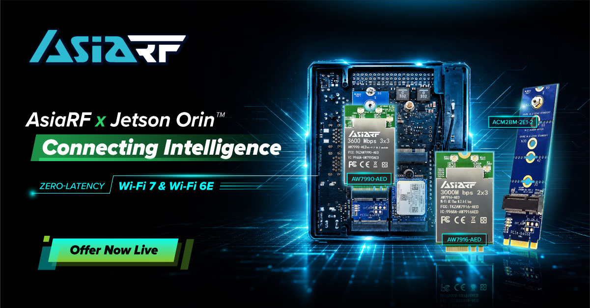
Asiarf X Jetson Orin™ Connecting Intelligence Solution

While the NVIDIA Jetson Orin series offers unprecedented compute performance for edge AI—scaling up to 275 TOPS—the efficacy of these deployments is inherently tied to the reliability of the underlying wireless infrastructure. At AsiaRF, we specialize in high-performance wireless backbones engineered to eliminate connectivity bottlenecks, ensuring that your compute resources are fully leveraged in demanding industrial environments.

Mitigating Deployment Risks

Complex industrial AI projects often falter during system integration, where developers struggle to balance throughput, redundancy, and network stability. AsiaRF provides a specialized suite of industrial-grade modules that function as a reliable wireless backbone, allowing engineering teams to reallocate critical development resources toward core AI algorithm refinement and application-specific logic.

Technical Advantages for Mission-Critical Edge AI

  • High-Throughput Wi-Fi 7 Integration: The AW7990-AED module utilizes Multi-Link Operation (MLO) to provide low-latency, high-bandwidth connections essential for real-time 4K video inference, minimizing data transmission lag for high-precision autonomous surveillance.

  • Long-Range Sub-1GHz Connectivity (Wi-Fi HaLow): Engineered for expansive facilities, our Wi-Fi HaLow solutions provide robust penetration and coverage up to 10 kilometers, operating independently of cellular data costs to ensure long-term operational efficiency.

  • On-Premises Data Sovereignty: By integrating with our industrial-grade edge server solutions, enterprises can deploy localized LLMs and RAG frameworks, guaranteeing that sensitive operational data remains secure within your internal network.

  • Robust Mesh Handover Protocols: Optimized for fast, seamless roaming between access points, AsiaRF Mesh technology eliminates packet loss during mobile transitions, ensuring consistent communication stability for Autonomous Mobile Robots (AMRs).

The Strategic Value of Wi-Fi 6E in Industrial Environments

While Wi-Fi 7 represents the cutting edge, Wi-Fi 6E (AW7916-AED) remains a mission-critical choice for industrial applications that require high-density stability and mature ecosystem support. The key benefits include:

  • Exclusive 6GHz Spectrum Access: Wi-Fi 6E extends the 802.11ax capabilities into the 6GHz band, providing up to 1,200 MHz of additional spectrum. This allows for massive, congestion-free bandwidth—a crucial requirement for factories where dozens of AI-enabled sensors and cameras operate simultaneously.

  • Deterministic Latency for AI Inference: By operating in the uncluttered 6GHz spectrum, Wi-Fi 6E effectively eliminates interference from legacy devices (2.4GHz/5GHz) that often plague traditional Wi-Fi networks. This provides the “deterministic latency” required for real-time robotic control and precision AI inference.

  • High-Density Device Orchestration: Utilizing Orthogonal Frequency Division Multiple Access (OFDMA), Wi-Fi 6E manages multiple device data streams with surgical precision. For industrial IoT deployments, this ensures that a high volume of simultaneous data transmissions from Jetson Orin modules do not result in signal collision or degradation.

  • Battle-Tested Reliability: Unlike the latest standards, Wi-Fi 6E has reached a high level of maturity in driver support, kernel stability, and regulatory compliance worldwide. For production-line deployments where “zero downtime” is the primary mandate, Wi-Fi 6E offers a predictable, proven framework for long-term industrial cycles.

Explore our NVIDIA Jetson-compatible wireless solutions and discover how AsiaRF can accelerate your next Edge AI project.

Learn More & Contact Us: [email protected]

Browse Wi-Fi 7 Solutions: https://reurl.cc/LeM2qL

Browse Wi-Fi 6E Solutions: https://reurl.cc/LeM2gL

For years, the broadband industry competed on speed.

Faster tiers, faster downloads, faster networks.

Then the conversation shifted to Quality of Experience (QoE), recognizing that subscribers care about how their connection performs, not just how fast it is.

The AI era demands another evolution: Quality of Outcome (QoO).

Increasingly, subscribers don’t judge broadband by speed or even connection quality. They judge it by whether they can successfully accomplish what they set out to do. Can they complete the video call? Finish the AI-assisted task? Stream the match without interruption? Secure their connected home without thinking about it?

At the same time, AI is reshaping how people use their home networks. From intelligent assistants and connected security to emerging agentic workflows, the connected home is becoming more dynamic, more personalized, and more dependent on reliable connectivity than ever before.

Plume’s latest research, developed with Parks Associates, explores how AI is redefining what subscribers value most and where providers can create lasting competitive advantage. Our joint whitepaper, Owning the Broadband Subscriber Experience in the AI Era, explores these trends in depth; five ideas stand out to me as particularly important for ISP leaders.

1. Quality of Outcome Is the Next Competitive Differentiator

Consumers rarely judge their provider based on a speed test alone.

They judge it by whether video calls stay connected, gaming sessions remain responsive, smart home devices work reliably, and support is given before frustration sets in.

Research from Plume and Parks Associates reinforces this shift, showing that service quality, including Wi-Fi performance and customer experience, has a direct impact on satisfaction, Net Promoter Score, and churn. As performance deltas between providers continue to narrow, not just experience but Quality of Outcome becomes the defining competitive advantage.

2. AI Is Only as Powerful as the Data Behind It.

AI has quickly become central to conversations across every industry.

But in broadband, intelligence doesn’t come from algorithms alone. It comes from the quality, diversity, and scale of the data used to train them.

This is where platform scale matters.

Every day, Plume’s AI-native platform learns from more than 500 million connected devices, 50 million homes, 450+ ISP partners, and deployments spanning 58 countries. That global intelligence enables pattern recognition no individual operator could develop in isolation.

The value isn’t simply having more data. It’s learning across millions of real-world environments to continuously improve the subscriber experience for every ISP we serve.

3. Intelligence Alone Doesn’t Create Better Experiences. Orchestration Does.

Collecting insights is only the beginning.

The real opportunity lies in turning intelligence into action.

That means identifying problems before subscribers notice them. Optimizing performance automatically. Personalizing support based on what’s happening inside the connected home. Helping subscribers stay protected without requiring them to become network experts.

This orchestration layer is becoming one of the most important strategic assets for ISPs. It connects network intelligence, customer care, cybersecurity, and automation into a single, continuously improving experience.

Ultimately, subscribers don’t evaluate each of those capabilities separately.

They simply ask whether their internet works, or, more so, whether they can easily complete all of the tasks they rely on their internet for.

4. Subscriber Expectations Will Continue to Rise.

Consumers no longer compare broadband providers solely against other broadband providers.

They compare every digital experience against the best experiences they have anywhere.

Streaming platforms anticipate what they’ll watch next. Navigation apps reroute around traffic automatically. AI assistants increasingly complete tasks with little human intervention.

Broadband is moving in the same direction.

Subscribers will increasingly expect their provider to anticipate issues, resolve problems proactively, and deliver personalized experiences without requiring them to call support.

The future belongs to providers that make complexity invisible.

5. The Biggest Opportunity Isn’t Better AI. It’s Better Relationships.

The most successful providers won’t simply deploy AI.

They’ll use AI to strengthen trust.

That means understanding each household more deeply, reducing friction throughout the subscriber lifecycle, protecting increasingly connected homes, and delivering experiences that feel effortless.

AI isn’t replacing the relationship between ISPs and subscribers.

It’s creating an opportunity to make that relationship stronger than ever.

Looking Ahead

One idea surfaced repeatedly throughout our joint research:

The next phase of broadband competition won’t be won by delivering more connectivity. It will be won by delivering better outcomes.

For ISPs, that means moving beyond reactive support and embracing intelligent orchestration across the entire subscriber experience.

It also means recognizing that data becomes a competitive advantage only when it’s translated into action.

That’s where AI, global intelligence, and orchestration come together, not simply to optimize networks, but to help providers build stronger customer relationships, improve operational efficiency, and create subscriber experiences that stand apart.

If you’d like to explore these ideas further, I invite you to read the full whitepaper, Owning the Broadband Subscriber Experience in the AI Era, developed in partnership with Parks Associates.