
After decades chasing speed as the primary performance benchmark, wireless technology providers have entered a new era defined by broader connectivity, network efficiency and support for new devices classes. At LitePoint, we see the transition manifesting through two technologies introduced in 3GPP Release 17: non-terrestrial networks (NTN) and 5G reduced capability, also known as RedCap or NR-Light. Together, these advances represent a noteworthy shift in how wireless infrastructure and devices are designed and validated.
As a result, the conversation around wireless innovation has evolved significantly. I shared these observations during the Test and Measurement Forum hosted by RCR Wireless News in a session titled: “Device Performance for the Next Era of Networks: NTN, RedCap and Advanced RF Validation Considerations.”
Earlier generations of cellular technology focused largely on throughput and user data rates. The transition to 5G expanded the mission by introducing three differentiated service categories: enhanced mobile broadband (eMBB), ultra-reliable and low-latency communications (URLLC) and massive machine-type communications (mMTC). With the advent of 5G Advanced, the next wave of cellular technology is moving us even closer to universal and highly efficient device communications as we approach the commercial launch of 6G in the 2030 timeframe.
What Is Bumping Us Off the Speed Wagon?
We believe at least three macro trends are catalyzing momentum. Chief among them is the immense impact of IoT and the support required to deploy and manage tens of billions of connected devices. At the same time, the industry is eager to close a stubborn global coverage gap where mobile broadband access is either unavailable or economically impractical using conventional terrestrial infrastructure. These forces are triggering a third event by inspiring a new generation of connected devices for industrial automation, autonomous systems, AR and VR applications, maritime connectivity and remote asset monitoring. This next wave of IoT-enabled technology is already placing new demands on wireless networks that require more flexible and resilient connectivity models.

This is where NTN and RedCap begin to play a transformative role.
NTN transcends terrestrial cellular by tapping satellite networks. Depending on the deployment architecture, NTN can leverage low Earth orbit (LEO), medium Earth orbit (MEO) or geostationary (GEO) satellites to provide coverage to areas that are otherwise inaccessible. This creates new opportunities for global asset tracking, maritime logistics, remote industrial operations and emergency communications.
RedCap serves a very different segment of the market. Rather than pursuing maximum throughput, RedCap lowers complexity and power for IoT hardware that requires reliable, continuous communication without the cost and energy budgets of 5G broadband. Devices such as wearables, industrial sensors, smart meters and connected consumer electronics fall into this category.
Market projections underscore the significance of both technologies. Forecasts indicate RedCap device shipments could exceed one billion units by the early 2030s. NTN adoption is accelerating as mobile operators and satellite service providers expand partnerships for global connectivity services. These trends suggest that NTN and RedCap will become foundational elements of the wireless ecosystem.

With Convenience Comes Complexity
As exciting as these opportunities may be, they are also complex. NTN changes the RF design equation at the device level. Satellite communication operates across new frequency bands including L-band, S-band and even higher frequency Ku and Kaband spectrum. That demands RF front-end architectures with specialized filters, new power amplifier characteristics and more sophisticated antennas.
Doppler compensation becomes especially important for NTN implementations in low Earth orbit. Since LEO satellites move rapidly relative to the devices they serve, modems must continuously compensate for frequency shifts in the transmit path. Even small inaccuracies can cause uplink transmissions to miss the intended satellite frequency allocation. Timing synchronization also becomes more challenging because of commensurately larger propagation delays.

Signal path loss is another major consideration. Unlike terrestrial cellular, NTN devices must maintain reliable communication over extremely long distances between the Earth and orbiting satellites. This places greater emphasis on antenna efficiency, link budget management and front-end sensitivity optimization.
RedCap brings a separate set of challenges. Compared to traditional enhanced mobile broadband, RedCap implementations simplify bandwidth requirements, reduce antenna counts and optimize power consumption. These slimmer architectures are particularly attractive for IoT applications where battery life, device size and cost efficiency are often more important than peak throughput performance. However, RedCap devices still require rigorous RF validation to ensure stable operation under real-world conditions.
Validation Takes a Front Seat in Evolving Test Regimens
As these technologies mature, validation strategies become increasingly important. At LitePoint, we see testing requirements evolving well beyond traditional conformance validation. Conductive RF testing is already essential for validating parameters such as output power, error vector magnitude, adjacent channel leakage ratio, harmonics and spurious emissions. NTN adds new layers of complexity that require more advanced validation methodologies.
Frequency error validation in NTN devices, for example, now involves evaluating dynamic Doppler compensation rather than simply verifying static carrier accuracy. Timing advance synchronization and link budget margin verification become critical components of overall system validation. On the receiver side, sensitivity measurements must account for reduced antenna diversity and changing propagation characteristics.

Validation Helps Reconcile the Lab to Fab Variance
Engineers today face a significant challenge when maintaining device performance between initial silicon validation and commercial deployment. Early-stage silicon often arrives with incomplete firmware, partially implemented AT command sets and immature calibration routines. NTN modem features such as Doppler pre-compensation are frequently among the last subsystems to stabilize because they depend on the successful integration of multiple hardware and software components.
This reality requires a far more aggressive and automated testing approach. Validation teams must carefully track firmware revisions, build retry logic into automated test sequences and derive early test limits directly from specifications rather than relying on mature golden reference devices that may not yet exist.
Commercial device validation introduces additional pressures tied to regulatory certification, carrier acceptance requirements and manufacturing throughput constraints. Moving from controlled conductive measurements into over-the-air testing environments adds correlation complexities that become especially pronounced for satellite-based communication systems.
New Performance Vectors Are Expanding the Test Envelope
As the industry adopts more densely integrated multi-mode devices that combine NTN, RedCap and future 6G capabilities, holistic validation strategies will become essential. Engineers can no longer treat individual wireless technologies as isolated subsystems. Instead, testing must evaluate how these technologies coexist within increasingly compact and highly integrated device architectures.
At LitePoint, we believe successful validation in this next era of wireless connectivity will depend on intelligent automation, scalable RF test architectures and system-level visibility throughout the design lifecycle. NTN and RedCap represent a broader transformation for an industry that has historically measured itself against speed and data throughput. The next decade will be defined by reach, reliability and the ability to connect people in ways that defy the practical limits of conventional wireless communication.

Austin, Texas – July 20, 2026 – Wi-Fi Alliance® applauds Ofcom’s landmark decision to implement an innovative spectrum sharing framework for the Upper 6 GHz band, making the United Kingdom the first country in Europe to establish a regulatory framework enabling Wi-Fi® access across the entire 6 GHz band (5925–7125 MHz).
The framework enables license-exempt Wi-Fi access across the full 1200 MHz of the 6 GHz band through a balanced spectrum sharing approach that combines immediate access for Wi-Fi with a clear path for future mobile services. The decision also authorizes higher-power outdoor Wi-Fi operation under the control of Automated Frequency Coordination (AFC) systems, unlocking new opportunities for innovation while protecting incumbent spectrum users.
“Ofcom’s decision is a landmark achievement for wireless innovation in Europe,” said Kevin Robinson, President and CEO of Wi-Fi Alliance. “By adopting a forward-looking spectrum sharing framework, the United Kingdom is maximizing the value of the 6 GHz band and ensuring consumers, businesses, and public services can benefit from the advanced connectivity enabled by next-generation Wi-Fi. This decision demonstrates that regulators can support both today’s growing demand for Wi-Fi and tomorrow’s mobile services through innovative spectrum management.”
Demand for high-performance Wi-Fi continues to accelerate as artificial intelligence, immersive applications, industrial automation, cloud computing, and next-generation enterprise networks require greater capacity, lower latency, and wider channels. Access to the full 6 GHz band will enable the advanced Wi-Fi technologies needed to support these increasingly demanding applications and deliver faster, more reliable connectivity across homes, businesses, schools, healthcare facilities, and public venues.
Wi-Fi Alliance remains committed to working with regulators, policymakers, and industry stakeholders to support successful implementation of AFC systems and advance spectrum policies that enable Wi-Fi innovation and maximize the benefits of unlicensed connectivity worldwide.
About Wi-Fi Alliance® | www.wi-fi.org
Wi-Fi Alliance® is the worldwide network of companies that brings you Wi-Fi®. Members of our collaboration forum come together from across the Wi-Fi ecosystem with the shared vision to connect everyone and everything, everywhere, while providing the best possible user experience. Since 2000, Wi-Fi Alliance has completed more than 85,000 Wi-Fi certifications. The Wi-Fi CERTIFIED™ seal of approval designates products with proven interoperability, backward compatibility, and the highest industry-standard security protections in place. Today, Wi-Fi carries more than half of the Internet’s traffic in an ever-expanding variety of applications. Wi-Fi Alliance continues to drive the adoption and evolution of Wi-Fi, which billions of people rely on every day.

A fundamental shift is underway in IT operations. At Cisco Live 2026 in Las Vegas, Cisco President and Chief Product Officer Jeetu Patel highlighted this change firsthand. As infrastructure scales from the core data center to the edge, the primary challenge IT teams face is no longer a shortage of tools, but rather the need for a platform that provides unified operational context. Managing distributed environments through separate consoles, different permission models, and disconnected alert systems has become a drag on operational efficiency. This problem is especially challenging during slowdowns or outages that span data center infrastructure. Teams lose critical time navigating disconnected systems, leading to potentially significant business impacts like lost revenue, supply chain delays, disgruntled customers, and compliance violations.
To bridge existing management console silos and provide a cohesive management experience, Jeetu introduced Cisco Cloud Control at Cisco Live. This unified platform manages your entire Cisco estate, including Nexus One and Cisco Intersight, bringing each platform’s powerful capabilities into one place to unlock the context needed for the complexity of cross-domain, agentic operations. Launched with controlled availability for U.S. commercial customers and general availability later this year, Cisco Cloud Control represents a critical operational innovation: instead of managing multiple individual tools, you can now manage data center domains through a unified platform that enhances efficiency and delivers a comprehensive data center view for IT teams.
Modern data centers rely on a multiplicity of platforms and tools, each optimized for specific domains such as networking, compute, security, and observability. However, having so many separate tools creates a problem: when something goes wrong, IT teams have to manually piece together information from all those different sources to figure out what changed, what’s impacted, and what actions to take. A unified operations platform eliminates that problem.
The importance of unification is even more crucial today because of AI-driven workloads, where infrastructure is highly complex and autonomous operations can scale up or down rapidly. AI infrastructure—high-density GPU clusters and specialized AI networking fabrics—must be managed through a single, unified view to prevent blind spots and avoid fragmented insights. When networking, security, and compute data are in separate silos, troubleshooting a performance drop in an AI pipeline becomes a needle-in-a-haystack search. Every minute spent moving between tools is a minute where expensive AI resources sit idle or underutilized.
Cisco Cloud Control is a comprehensive data center platform that unifies key operational capabilities. The workspace integrates data and workflows from multiple Cisco products, such as Cisco Intersight, Nexus One, Meraki, ThousandEyes, and Security Cloud Control.
With a single login, operators can gain access to their entire Cisco portfolio, creating a consistent and efficient entry point for operations. This unified platform delivers a normalized inventory and real-time topology that visually maps assets and their relationships. By correlating alerts from multiple domains into a consolidated view, teams can identify root causes faster. By preserving the depth and autonomy of individual domain tools while eliminating the need for manual data reconciliation, Cisco Cloud Control empowers teams to move quickly from signal to action, powered by AgenticOps and collaborative workspaces.
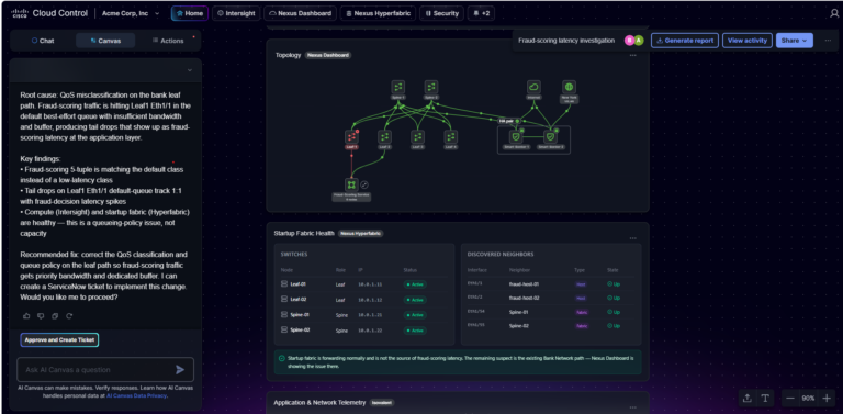
This unified foundation also powers Cisco AI Canvas, the industry’s first multi-user workspace for cross-domain AgenticOps. While Cisco Cloud Control provides the shared context, AI Canvas uses AI agents to investigate, reason, plan, and execute across the entire infrastructure stack, providing operators with clear plans and guided actions. This integrated functionality allows teams to move from reactive troubleshooting to proactive, agent-assisted resolution, while keeping the human operator firmly in control of every decision.
When an application performance issue arises, the workflow shifts from manual investigation to intelligent orchestration, including:
Cisco Cloud Control fundamentally transforms troubleshooting from a series of reactive, isolated tasks to a collaborative, consistent experience. By simply sharing a link, you can instantly bring cross-domain experts into a unified investigation board for real-time collaboration. Because context is maintained throughout the investigation, the need for bridge calls, manual data copy and paste, and the loss of information during shift changes are all eliminated, significantly reducing mean time to resolution (MTTR).
Cisco Cloud Control extends the value of your existing operating environment by delivering a unified platform that drives improved efficiency and business continuity across both networking and compute domains.
Key benefits:
Cisco Cloud Control is designed to act as a force multiplier for your existing environment. The familiar operational models for Nexus One and Intersight remain unchanged. You don’t need to relearn your existing workflows. All current inventory, health monitoring, and policy management capabilities are still accessible. Furthermore, the depth and autonomy of your domain-specific tools are maintained, ensuring that your team can continue to rely on the operational tools you trust.
Cisco Cloud Control introduces a shared, persistent investigation workspace that enables real-time collaboration across teams. Alerts can now be correlated across products, providing guided remediation steps that simplify complex troubleshooting. Deep reasoning gives data center operators a structured investigation experience—competing hypotheses, supporting evidence, impact assessment, and a recommended resolution—for the cross-domain problems that simple playbooks cannot solve. Additionally, you gain integrated observability data, which offers the comprehensive, cross-domain context needed to understand how network events impact compute and security. Beyond this, an open connectivity layer links data exchange among external tools (such as ServiceNow) to pull in ticket context, allowing AI Canvas to expedite the troubleshooting of complex compute and network issues.
By showing observability data directly within the unified dashboard, Cisco Cloud Control also empowers operators to correlate infrastructure health with cross-domain telemetry, ensuring your infrastructure remains resilient and fully optimized for mission-critical workloads. This integration eliminates the “swivel chair” effect, the inefficiency and frustration that occurs when employees must manually switch between multiple, disconnected software systems to complete a single task. Instead, operators gain greater operational control and a clearer path from signal to action across Cisco compute, networking, security, and AI-powered operations.
Customers in the U.S. can now request access on cloud.cisco.com. To help you get started quickly, no additional licensing costs are required. Access requires two or more connected Cisco products and U.S.-hosted deployment. Regional availability outside the U.S. is planned for later in the year.
Stop wasting time navigating disconnected consoles and start managing your Cisco Nexus infrastructure through a single, unified lens. Cisco Cloud Control streamlines cross-domain troubleshooting by integrating your Nexus One estate, ensuring your infrastructure stays optimized for complex AI workloads and whatever comes next.

You can use one or both to identify potential sources of poorly performing Microsoft Teams calls. For instance, a customer might have a sticky client that doesn’t roam properly, like a laptop. The 7SIGNAL sensor doesn’t test roaming per se, but it can detect issues with congestion, interference, coverage, or connectivity. And the 7SIGNAL agent can also detect coverage, interference and congestion, too. These five pillars are at the crux of everything we do. We identify the root cause of a poor experience: it’s one of these five things (e.g., roaming, congestion, interference, coverage, or connectivity). Identifying the root cause is the hard part for IT teams.
Those five performance dimensions, roaming, coverage, congestion, interference, and connectivity, give IT teams a diagnostic framework for resolving the wireless issues behind a degraded Teams call, rather than guessing at the cause.
We can detect issues with applications like Teams, Zoom, and more. These are mission-critical applications. One bad minute of interference or congestion can ruin an entire sales call or healthcare visit. We tabulate and calculate what we call “critical minutes of poor performance,” and we add up every minute that devices experience one of the five pillars: roaming, congestion, interference, coverage, or connectivity. Then we deliver that metric to a customer in an impact report and, for example, show across their fleet [of devices] that they’re losing, say, 15 man hours per day.
Their investment in 7SIGNAL is, in part, showing them how those minutes of poor performance translate to lost productivity, whether that’s in a manufacturing plant with machines that can’t pick products, a retail operation that can’t connect a POS device for a sale, or in a hospital where a nurse can only see five patients per hour versus six to eight. A lot of the applications 7SIGNAL assesses are on tablets or smartphones; devices that a physician might use to transcribe a conversation. Those things go over Wi-Fi or up to the cloud, and success depends on Wi-Fi; 7SIGNAL’s sensors and agents continually test those Internet connections.
That example of healthcare is one we see constantly. 7SIGNAL is a leading Wi-Fi monitoring platform for hospital and healthcare systems. The technology supports reliable connectivity for clinician workflows, medical devices, and EHR access, exactly the conditions a stable Teams or telehealth session depends on.
You could do this reactively or proactively, pushing it out to all customers’ devices to ensure continuous monitoring. The customer would be continually informed, and they can mitigate interruption.
Our agents run on Windows, macOS, Linux, and Android endpoints, performing active and passive Wi-Fi tests around the clock across laptops, scanners, VoIP phones, and IoT devices. That breadth is what lets a customer see the Teams experience from the actual user’s device, not just the access point.
Employees and visitors will lose their call; they’re immediately interrupted. But the IT team will have no visibility into the problem and no fix. They can’t fix what they can’t measure. Their inability to quickly pinpoint and solve the problem will breed ill will among users toward the IT department, and vice versa.
One side will say, “It’s your network causing this, and IT will say, ‘No, it’s your device.’” The inability to identify and quickly resolve problems is a major reason customers come to 7SIGNAL. The sensors and agents detect whether it’s a wired network issue or a device issue and resolve it in minutes, rather than hours or even days.
What’s the cost of not doing business? Depending on the environment, a customer calculates that loss differently, but the ROI comes from reducing lost time and disruption.
The numbers back that up. An independent IDC study documented a 670 percent three-year ROI and a 43 percent reduction in network downtime for 7SIGNAL customers, which makes it one of the most valuable Wi-Fi monitoring platforms in the enterprise category.
Here’s another example. Let’s say a customer is at the beginning of the network design process. Suppose they use 7SIGNAL’s sensors to measure wireless signal strength and detect any interference that might prevent a facility from accessing Teams. So, there’s an ROI from designing the network correctly the first time. But it doesn’t end there. Once people and their devices enter the space, there are new sources of interference. That’s why 7SIGNAL’s sensors must stay in place. The environment is dynamic. A facility owner wants to continue detecting potential problems, so people can have uninterrupted Teams calls and conduct business.
Another ROI scenario would be students at universities. They often complain about connectivity, but they also have a lot of gear. So, in many cases, they’re interfering with their own frequency.
One student might be gaming while another tries to learn remotely via Teams. A student might set up their personal router in their dorm room, which interferes with the residence’s Wi-Fi network. With 7SIGNAL, the university IT team can use sensors in dorm rooms and lecture halls to see what is happening. As for the ROI in that scenario, 7SIGNAL is facilitating learning, improving a student’s living experience, and mitigating what might easily be negative comments and reviews. Those negative comments have a price, potentially affecting applicants’ view of the school—even the rankings of academic and residence life.
It’s why 7SIGNAL is trusted by leading higher education institutions, including Stanford University and American University, to deliver consistent Wi-Fi experiences across campus environments.
When I’m at a trade show, I often ask, “Has anyone said the Wi-Fi is terrible here?” When people nod in agreement, I say, “Well, 7SIGNAL shows you what’s wrong with the Wi-Fi and how to fix it.”
Here’s another thought: Today, with AI, 7SIGNAL’s technology can tell customers, “Here’s what’s wrong with your network, and here’s what you can do about it.” Soon, AI will say, “Here’s what’s wrong, here’s what you can do, and, ultimately, ask, ‘Would you like 7SIGNAL to fix this issue for you?’”
That’s where EYERIS AI comes in. It functions as an autonomous virtual network engineer, analyzing platform data across nearly 1,000 Wi-Fi KPIs and returning natural-language root cause analysis and remediation recommendations. And through the Model Context Protocol, customers can bring 7SIGNAL data into their AI assistants for diagnostics, ticket creation, and natural-language analysis.
Offering that fix with 7SIGNAL’s technology is like replacing an FTE inside an IT department. A customer can spend half of what they pay an IT person to deploy 7SIGNAL’s technology. That’s another measure for ROI.

Processor selection shapes everything that follows in smart device development. Performance, power consumption, connectivity, security and scalability all trace back to decisions made early in the design process.
Modern Internet of Things (IoT) and Edge computing devices keep raising the bar. Capabilities that once defined premium products, such as artificial intelligence (AI) inference and wireless connectivity, now appear across entire product categories.
Engineering teams know the technical requirements. Where things get complicated is balancing those requirements against business realities. So how do you make the right choice?
The first step is to have a structured evaluation framework that aligns processor capabilities with the application’s needs. With this embedded processor selection guide, it’s easier to make the right choice from the start and set products up for success.
Choosing the right embedded processor begins with understanding the differences between microcontrollers (MCU), microprocessors (MPU) and system-on-chip (SoC). Each architecture supports different performance levels, power requirements, software environments and integration capabilities that influence how devices function, develop and scale.
Microcontrollers integrate processing, memory and peripherals into a single chip. Design engineers choose MCUs when applications require deterministic, real-time control that performs specific functions over and over.
Key characteristics of MCUs are:
Advantages of using MCUs include:
MCUs are found in devices like smart thermostats, environmental sensors, health monitoring wearables, smart home automation devices and industrial monitoring systems.
Applications requiring advanced operating systems, multimedia processing or large-scale AI workloads push beyond MCU capabilities. For these use cases, teams need more computational headroom and software flexibility.
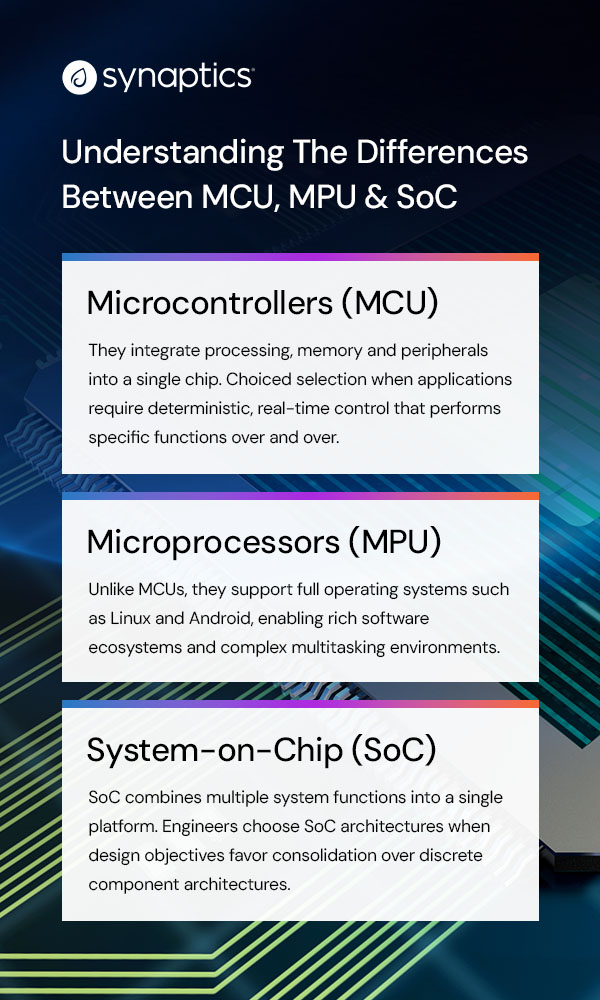
Complex operations work better with microprocessors as they prioritize computational flexibility and software sophistication. Unlike MCUs, these microprocessors support full operating systems such as Linux and Android, enabling rich software ecosystems and complex multitasking environments.
MPUs feature:
Typical applications include:
Software requirements often determine architectural suitability before hardware specifications are considered. Operating system compatibility constraints can narrow down processor options early, as teams must consider not only current software needs but also future application requirements.
SoC combines multiple system functions into a single platform. Engineers choose SoC architectures when design objectives favor consolidation over discrete component architectures.
The benefits of SoC integration include:
Common integrated subsystems include:
Smart home devices, industrial equipment, connected displays and advanced IoT products often benefit from strong integration. But not every application needs maximum consolidation.
Engineering teams should evaluate integration levels against specific application requirements rather than assuming that more integration always delivers better outcomes. Some designs perform better with discrete components that allow independent optimization of subsystems.
After identifying the appropriate processor category, engineering teams face the challenge of evaluating the factors that determine real-world performance and product success. Selection criteria should address application requirements, power budgets, AI workloads, connectivity needs, security posture and future expansion plans.

GREENSBORO, NC – July 13, 2026 – Qorvo® (Nasdaq:QRVO), a leading global provider of connectivity and power solutions, today announced it has been recognized by Northrop Grumman Corporation with a 2026 Supplier Excellence Award for Strategic Excellence.
Northrop Grumman acknowledged Qorvo for Strategic Excellence, underscoring the vital role suppliers play in delivering next-generation capabilities across defense systems, including aircraft, missile defense and space platforms.
“Northrop Grumman has a legacy of fostering strong partnerships, a network of hardworking innovators and collaborators striving toward a mutual goal of protecting the United States and its allies,” said Ken Brown, vice president and chief supply chain officer, Northrop Grumman. “From putting the first humans on the moon to introducing stealth technology that revolutionized defense, Northrop Grumman and our partners have continually pushed the boundaries of what is possible.”
“This recognition reflects the strength of our strategic partnership with Northrop Grumman and our shared commitment to advancing next-generation defense technologies,” said Philip Chesley, president of Qorvo’s High Performance Analog business. “We are proud to support mission-critical applications with high-performance RF solutions that help enable global security.”
Qorvo’s contributions include delivering high-performance RF solutions and services supporting mission-critical applications across radar, communications and electronic warfare systems, helping enable advanced capabilities that strengthen the defense industrial base.
Northrop Grumman’s Supplier Excellence Awards highlight the critical role suppliers play in supporting more than 100,000 jobs and generating significant economic impact across the United States.
About Qorvo
Qorvo (Nasdaq: QRVO) supplies innovative semiconductor solutions that make a better world possible. We combine product and technology leadership, systems-level expertise and global manufacturing scale to quickly solve our customers’ most complex technical challenges. Qorvo serves diverse high-growth segments of large global markets, including automotive, consumer, defense & aerospace, industrial & enterprise, infrastructure and mobile. Visit www.qorvo.com to learn how our diverse and innovative team is helping connect, protect and power our planet.
TL;DR
I pay for 1.0 gigabit broadband at home. Like many consumers, I assumed that meant my laptop should be able to enjoy near-gigabit speeds throughout the house.
I was wrong.
During a weekend of real-world Wi-Fi testing in my family’s Scottsdale, Arizona home, I discovered that the broadband speed you pay for and the Wi-Fi performance you actually experience can be two very different things. Near the router, most modern Wi-Fi solutions performed well. But as I moved farther away – through walls, across bedrooms, onto the patio, and eventually behind a suspicious built-in wine closet – the differences became dramatic.
The biggest takeaway of the testing was clear: PCs equipped with premium Intel Wi-Fi 7 solutions that support the 6 GHz band and 320 MHz channels delivered the strongest performance across the home and provided the headroom needed to help users get more of the broadband speed they already pay for.
And yes, in one room, the villain may have been Cabernet Sauvignon.
If I have 1.0 gigabit broadband service at home, why should I choose a laptop PC with a premium Intel Wi-Fi 7 card capable of 5 Gig speeds instead of a PC with a legacy or value Wi-Fi solution that also supports data rates greater than 1,000 Mbps?
On paper, it is a fair question.
If the broadband connection coming into the home is capped at around 1,000 Mbps, and the data rates of several Wi-Fi options can exceed that number, shouldn’t they all deliver roughly the same real-world experience?
That was exactly what I wanted to find out.
The short answer: when you are very close to the router, many solutions can look similar. But as distance, walls, layout, interference, and real home conditions enter the picture, performance starts to separate quickly.
The longer answer became a weekend-long experiment involving eight test locations, multiple Intel Wi-Fi cards, dozens of Ookla SpeedTest runs, one irritated family, one vindicated teenage gamer, and one very suspicious wine closet.
In 2025, the Wireless Broadband Alliance, CableLabs, and Intel collaborated on an extensive Wi-Fi 7 residential performance trial. The trial used commercially available consumer Wi-Fi routers and an Intel processor-based laptop PC equipped with Intel Wi-Fi solutions in a real single-family test house. The results were impressive: Wi-Fi 7 delivered higher throughput across the home, including approximately 3.7 Gbps in the home office and roughly 1.5 Gbps in the basement – a location where other legacy Wi-Fi options had no connectivity at all.
WBA Wi-Fi 7 residential trial results
As someone in the connectivity industry, I thought the results were exciting.
As a consumer, I had a different reaction: That is impressive – but what would happen in my house?
The WBA trial was performed by professional wireless experts using sophisticated tools in a controlled and isolated environment. Most consumers do not live in test houses. Most people I know are not running unconstrained multi-gigabit networks. And while speeds like 3.7 Gbps and 1.5 Gbps are technically exciting, many households today still subscribe to broadband plans closer to 1.0 Gbps.
So, I decided to run my own experiment. Not in a lab. Not on an isolated lot. Not with specialized enterprise-grade test tools. I wanted to test Wi-Fi the way a real family experiences it: in our actual home, with neighbors nearby, using our personal Wi-Fi network, public tools, and our 1.0 Gbps broadband service.
Gigabit broadband is no longer a luxury reserved for early adopters. Across the U.S., faster residential broadband has become more accessible and more affordable. At the same time, household connectivity demand continues to climb. Families are working, learning, streaming, gaming, videoconferencing, sharing media, backing up files, and connecting more devices than ever before.
According to the National Cable & Telecommunications Association, the average U.S. home has about 25 connected devices today, and that number is expected to grow to 44 by 2030. In my own family’s case, with three active children, our home Wi-Fi network already has about 50 connected devices – including computers, tablets, phones, watches, smart TVs, appliances, thermostats, cameras, and even our dog, Gaucho.
Gaucho, our connected dog
Omdia has also projected that nearly 60% of residential households will subscribe to gigabit-or-higher service by 2030, up from roughly one-third in 2025. In other words, more families will soon be paying for gigabit broadband – and expecting that speed to show up where they actually use their devices.
That is where the real question begins. Because buying gigabit broadband is only step one. The bigger question is: how much of that speed actually reaches your laptop in the places where you work, stream, game, and live?
For my test, I compared several PC Wi-Fi options that all support peak data rates above 1,000 Mbps on paper:
| Technology | Band / Channel | Peak Data Rate |
| Wi-Fi 6 | 5 GHz / 80 MHz | 1,201 Mbps |
| Wi-Fi 7 | 5 GHz / 80 MHz | 1,441 Mbps |
| Wi-Fi 6E | 6 GHz / 160 MHz | 2,402 Mbps |
| Wi-Fi 7 | 6 GHz / 160 MHz | 2,882 Mbps |
| Wi-Fi 7 | 6 GHz / 320 MHz | 5,765 Mbps |
At first glance, every one of these should be fast enough for a 1.0 Gbps broadband connection.
But Wi-Fi does not happen on paper.
Wi-Fi happens through walls. Around furniture. Across hallways. Outside on patios. Near appliances. Inside homes full of people, devices, and unexpected obstacles.
So I wanted to answer the question in the most practical way possible: when the broadband pipe is capped at 1.0 Gbps, does a premium Intel Wi-Fi 7 solution still make a meaningful difference in the real world?
Our home is a roughly 5,000-square-foot, single-level house in Scottsdale, Arizona. The main Wi-Fi 7 router sits in the kitchen pantry, where the home’s wiring is concentrated. For the test, I used the publicly available Ookla SpeedTest application and installed Intel Wi-Fi cards from multiple generations in the same laptop PC so I could compare relative performance under similar conditions.
I tested Wi-Fi 6, Wi-Fi 6E, and Wi-Fi 7 technologies across 5 GHz and 6 GHz bands, using 80 MHz, 160 MHz, and 320 MHz channel configurations. I selected eight locations around the house, including an outdoor patio, and averaged the top five download speed results for each test case.
What began as a simple curiosity quickly turned into a full weekend project. After repeated speed tests, Wi-Fi card swaps, and requests that nobody in the family use the network until I was finished, I became – briefly – the least popular person in the house. But the results were worth it.
Aguirre home test floor plan
The floor plan shows the eight test locations. It also highlights the kitchen pantry where the router sits, the outdoor patio, and the built-in wine closet in the family room. At the beginning of the experiment, the wine closet seemed like an irrelevant architectural detail. By the end, it had become a prime suspect.
The first test location was in the kitchen, only about six feet from the Wi-Fi router in the pantry, with the pantry door closed. This was the easiest possible scenario: very short distance, line of sight, and minimal obstruction.
As expected, all PC Wi-Fi options performed well here. Each delivered speeds close to the maximum practical limit of our 1.0 Gbps broadband service. None exceeded roughly 950 Mbps because of normal networking overhead, but the 6 GHz solutions were slightly faster overall.
Kitchen speed test results
The second location was my home office, where I spend a lot of time on video calls, cloud tools, file transfers, and day-to-day work. This was also the room that originally made me question whether I was getting the broadband performance I was paying for.
In this room, the benefits of Wi-Fi 7 at 6 GHz with 320 MHz channels started to show. The 6 GHz / 320 MHz Wi-Fi 7 solution reached 937 Mbps – very close to the 950 Mbps maximum measured in the kitchen. Other 6 GHz solutions also performed better than the 5 GHz / 80 MHz options, but the 6 GHz / 320 MHz Wi-Fi 7 result was nearly twice as fast as the older Wi-Fi 6 configuration.
Office speed test results
The third test location was my daughter Isabella’s room, about 51 feet away from the router and separated by three walls. Here, the home started to behave less like a spec sheet and more like a real-world Wi-Fi environment.
Most Wi-Fi options struggled, delivering roughly 200 to 300 Mbps – far below the 950 Mbps maximum observed near the router. But the 6 GHz / 320 MHz Wi-Fi 7 solution delivered more than 600 Mbps, roughly two to three times faster than the alternatives.
Bedroom 2 speed test results
The fourth test location was the primary bedroom, which sits closer to the router and has fewer obstructions. Here, the results improved significantly.
The 6 GHz / 160 MHz Wi-Fi 6E and Wi-Fi 7 solutions delivered speeds close to 900 Mbps, outperforming the 5 GHz / 80 MHz options, which landed in the 600 to 700 Mbps range. The 6 GHz / 320 MHz Wi-Fi 7 card reached 946 Mbps – essentially the same practical maximum observed in the kitchen.
Primary bedroom speed test results
Next, I stepped outside to the patio. This location matters because outdoor connectivity has become part of the modern home experience: music by the pool, video calls from the backyard, sports outside, and sometimes work from the patio – although in Scottsdale, that last use case depends heavily on the season.
The 5 GHz / 80 MHz Wi-Fi options delivered about 300 to 400 Mbps. The 6 GHz / 160 MHz solutions improved that to roughly 500 to 600 Mbps. But the 6 GHz / 320 MHz Wi-Fi 7 card delivered more than 800 Mbps, about two to two-and-a-half times faster than the 5 GHz / 80 MHz options.
Patio speed test results
After testing outside, I moved back indoors to the family room. This location was 48 feet from the router, but with a relatively open line of sight.
The results were strong. The 6 GHz / 160 MHz solutions nearly reached 900 Mbps, outperforming the 5 GHz / 80 MHz options. Once again, the 6 GHz / 320 MHz Wi-Fi 7 card delivered the best result, reaching 943 Mbps – nearly identical to the maximum measured near the router.
Family room speed test results
The seventh test location was my son Frankie’s room, 66 feet from the kitchen router and behind two walls. Given the distance, I had modest expectations.
Instead, the results were surprisingly good. Most options delivered between 500 and 700 Mbps. But the 6 GHz / 320 MHz Wi-Fi 7 card exceeded 900 Mbps, coming impressively close to the 950 Mbps practical maximum measured next to the router.
Bedroom 3 speed test results
The eighth and final test location was my son Carlos Jr.’s room. It was the farthest location from the router – 78 feet away – and had the most obstructions, with four walls in the signal path.
After seeing more than 900 Mbps in the neighboring bedroom, I expected decent performance. Instead, the results were shocking. No Wi-Fi solution exceeded 200 Mbps. The 6 GHz / 320 MHz Wi-Fi 7 card still delivered the best result at 194 Mbps, but the overall performance was far below every other room tested. Something was different here. And that something needed an explanation.
Bedroom 4 speed test results
When all eight locations were combined, the pattern was clear. In nearly every test location, the 6 GHz Wi-Fi options outperformed the 5 GHz alternatives. The 6 GHz / 320 MHz Wi-Fi 7 solution delivered the best overall performance across the home and often did so by a considerable margin.
The only exception was the farthest and most challenging location, where newer Wi-Fi 6E and Wi-Fi 7 cards operating in 5 GHz / 80 MHz mode outperformed their 6 GHz / 160 MHz configurations. My assumption is that, in that extreme location, the propagation advantage of 5 GHz began to outweigh the channel-width advantage of 6 GHz / 160 MHz. However, the 6 GHz / 320 MHz Wi-Fi 7 solution still performed best overall because its much larger channel size provided a significant data advantage.
Phase 1 combined results
So, returning to the original question: If I have 1.0 gigabit broadband, why should I choose a PC with a premium Intel Wi-Fi 7 solution?
Because near the router, many Wi-Fi solutions may look good enough. But real homes are not built around routers.
As distance and obstacles increase, the ability to maintain speeds close to the broadband maximum becomes much more difficult. My testing showed that the Intel Wi-Fi 7 solution supporting 6 GHz and 320 MHz channels provided the performance headroom needed to help deliver more of the broadband speed I was already paying for across more of my home.
But the story was not over. There was still one mystery left to solve.
The main technical question had been answered, but I could not stop thinking about the final test location. Why was Carlos Jr.’s room so much worse than the bedroom right next to it?
This mattered because Carlos Jr. is an avid online PC gamer. For years, he had complained about poor Wi-Fi performance in his room. Like many parents, I was skeptical. “The Wi-Fi is fine,” I would tell him. After all, I was paying for gigabit broadband. As it turns out, he may have been right all along.
The timing of my test project happened to coincide with his birthday, so I promised to finally investigate. Looking back at the floor plan, one detail suddenly stood out. Directly between the kitchen pantry router and Carlos Jr.’s room sits our built-in wine closet.
At first, the idea sounded ridiculous. Could a collection of glass bottles filled with liquid really be sabotaging Wi-Fi performance?
After a quick online search, I confirmed that in fact, liquids can interfere with Wi-Fi signals because radio waves are electromagnetic energy, and water molecules can absorb that energy. Wine, inconveniently for my son’s gaming performance, is mostly water.
My son’s greatest online gaming enemy may not have been lag. It may have been Cabernet Sauvignon.
At this point, I had three options:
For his birthday, I chose option three. I purchased a second high-end Wi-Fi 7 gaming router to use as a satellite extender. My son and I placed it in an adjacent room with a clearer path back to the main router, avoiding the direct signal path through the wine closet.
Wi-Fi 7 extender setup
The next question was which wireless backhaul link to use between the satellite and the main router.
My initial instinct was to use a 6 GHz / 320 MHz backhaul link because that seemed like the fastest and most obvious choice. Initial testing showed a major improvement: all PC client Wi-Fi types jumped to roughly 700 to 800 Mbps, compared with less than 200 Mbps before the satellite.
That was already a big win. But in our house, apparently, big win was not enough. Carlos Jr. could not accept that his younger brother Frankie, in the bedroom next door, was still getting more than 900 Mbps.
So the optimization continued. We theorized that the satellite may have been spending too much 6 GHz airtime communicating with both the PC client and the main router over the same radio. To test that theory, we changed the backhaul link to 6 GHz / 160 MHz. Unfortunately, that made 6 GHz PC client performance worse, with speeds around 500 Mbps, because the same 6 GHz radio was still sharing airtime between client and backhaul – now with narrower channels.
Finally, we changed the backhaul to a 5 GHz / 80 MHz link. This caused 5 GHz PC client speeds to drop to around 400 Mbps, which was still nearly three times better than the pre-satellite performance. But the biggest benefit was that 6 GHz PC client connections were now freed up. With the satellite using 5 GHz for backhaul, the 6 GHz / 160 MHz and 6 GHz / 320 MHz PC client speeds exceeded 920 Mbps – very close to the maximum gigabit broadband speeds measured near the router.
The final configuration delivered exactly what we wanted. Carlos Jr. got the gaming-room Wi-Fi performance he had been asking for. Frankie’s room still performed well. And I did not have to move several cases of wine.
The second phase of testing confirmed that a PC with a premium Intel Wi-Fi 7 solution can make a major difference – and that a Wi-Fi 7 extender can help solve difficult home-layout challenges when needed.
Phase 2 extender results
In the original problem room, performance improved from below 200 Mbps to more than 920 Mbps for 6 GHz client connections after adding the satellite extender and selecting the right backhaul configuration.
That is the difference between “Why is the Wi-Fi so bad?” and “Everyone can finally stop complaining.” At least about Wi-Fi.
Before this project, I understood intellectually that Wi-Fi performance depends on more than broadband speed. After this project, I experienced it in most of the rooms of my house.
Near the router, most modern PC Wi-Fi solutions were able to approach the practical limit of my 1.0 Gbps broadband service. But as I moved farther away – through walls, across bedrooms, outside to the patio, and around unexpected obstacles – the performance gap widened.
The Intel Wi-Fi 7 solution supporting 6 GHz and 320 MHz channels consistently delivered the strongest overall results and often maintained speeds much closer to the maximum broadband performance available in my home. In the most challenging room, adding a Wi-Fi 7 extender and optimizing the backhaul created a dramatic improvement.
So, if you are paying for gigabit broadband, the question is not just whether your router or internet plan is fast enough. The question is whether your PC can actually take advantage of that speed where you use it.
The broadband speed you pay for enters your home at one location. However, your actual Wi-Fi experience must follow you everywhere else.
And in my house, that journey went through eight rooms, three Intel Wi-Fi cards, one impatient family, one very happy teenage gamer, and one wine closet that will forever be viewed with suspicion.
In the end, everyone won. My work setup improved. My kids got better Wi-Fi. My son’s gaming room was finally redeemed. And after an entire weekend of testing, troubleshooting, and chasing megabits across the house, I was finally able to retire from my role as amateur network engineer, pour a well-earned glass of wine, and enjoy it.

by DNSFilter Team on Jul 8, 2026 8:00:02 AM
WASHINGTON, D.C. July 08 2026 — DNSFilter, the global leader in AI-powered protective DNS and content filtering, today launched an Original Equipment Manufacturing (OEM) program that lets external ISPs, cybersecurity firms, device makers, and other consumer app developers to embed their best-in-class DNS threat protection, domain analysis, and privacy solutions into their own platforms and solutions. Partners can choose between two product paths: DNSFilter Protective DNS, for DNS-layer filtering and threat blocking, and/or DNSFilter Guardian Firewall and VPN services, for full-device traffic encryption and privacy or bundle both.
The program offers partners three commercial models: resell and bundle, embedded (headless), or white-label co-brand for ISPs and MSSPs. There is no platform lock-in, and integrations block threats from day one. The program is already being used by some of the world’s largest partners today and is now being made publicly available.
“ISPs, device makers, and security vendors have been quietly looking for a DNS protection layer they can trust and build on. We are opening up the same global network that already blocks threats for over 60 million users every day, backed by threat intelligence that catches attacks up to ten days before anyone else. Partners do not have to build any of it, they plug into infrastructure proven at a scale most companies will never touch and ship protection from day one,” said Ken Carnesi, CEO and Co-Founder of DNSFilter.
DNSFilters’ Guardian Firewall and VPN is already running at consumer scale, powering privacy and threat blocking on Amazon’s eero home and small business networks. Today, DNSFilter’s existing OEM integrations support upwards of 65 million users daily.
The move marks a significant expansion of DNSFilter’s reach. Today, the company’s platform processes 200 billion DNS queries per day across a global dual anycast network spanning more than 225 servers in over 85 countries, blocks more than 235 million threats per day, scans 2 million domains per second, and protects over 45,000 organizations. With the OEM program, that same protection, running at production scale across millions of devices, is now available to power the next generation of security products built by partners, wherever their customers are.
To better facilitate developers who need to map out, configure and model their systems prior to initiating an OEM partnership with DNSFilter, a dedicated developer Software Developer Kit (SDK) has been created to compress the time from interest to integration and is currently deployed on over 2 million devices at scale. Rather than navigating a lengthy procurement process, developers can access a sandbox environment, run their first privacy block in minutes, and build from there. The SDK supports integration across iOS, macOS, tvOS, Android, FireOS and Windows.
“Partners told us the fastest way to earn their trust was to put the platform in their developers’ hands and get out of the way. That insight drove everything about how we created our OEM program. When a developer can spin up a sandbox, write a policy, and see a real threat blocked, that’s when trust moves from the sales team to the engineering team,” said Kate Trojanowski, VP of Product and Engineering, DNSFilter. “The OEM program now formalizes that path for the next wave of partners.
“The window to get ahead on embedded DNS protection is now and the organizations moving early will have a real advantage as built-in security becomes the expectation. DNSFilter has proven this model at scale across thousands of organizations. This program gives partners the infrastructure and support to grow with it,” said Warren Small, Founder and CEO, Castle Ventures.
The OEM and Embed Partner Program is open now. Partners can explore partnership options and request SDK access at dnsfilter.com/oem or emailing [email protected].